Diese Anleitung enthält neuere Änderungen. Wechsel zur neuesten unüberprüften Version.
Einleitung
If your front camera isn't working as needed, just replace it! This guide will teach you how.
Was du brauchst
-
-
Heat the iOpener for thirty seconds.
-
Throughout the repair procedure, as the iOpener cools, reheat it in the microwave for an additional thirty seconds at a time.
-
-
-
Remove the iOpener from the microwave, holding it by one of the two flat ends to avoid the hot center.
-
-
-
Fill a pot or pan with enough water to fully submerge an iOpener.
-
Heat the water to a boil. Turn off the heat.
-
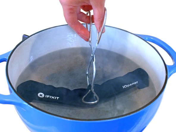
Place an iOpener into the hot water for 2-3 minutes. Make sure the iOpener is fully submerged in the water.
-
Use tongs to extract the heated iOpener from the hot water.
-
Thoroughly dry the iOpener with a towel.
-
Your iOpener is ready for use! If you need to reheat the iOpener, heat the water to a boil, turn off the heat, and place the iOpener in the water for 2-3 minutes.
-
-
-
Handling it by the tag, place the heated iOpener across the bottom casing.
-
-
-
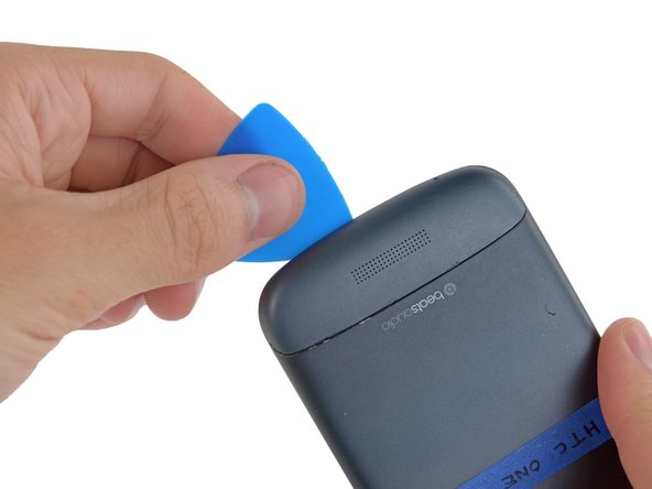
Gently place an opening pick in the corner of the gap between the bottom casing and rear case.
-
Slide the opening pick along the side of the casing, prying it away from the adhesive as you go.
-
-
-
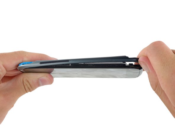
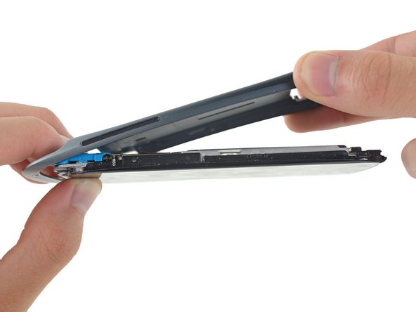
Starting at the groove near the headphone jack, use a plastic opening tool to lift the top casing.
-
-
-
Remove the following screws holding the rear case to the rest of the phone:
-
Two 3.15 mm Phillips #00 screws
-
One 4.15 Torx T5 screw
-
One 4 mm Torx T5 screw
-
-
-
-
Place your fingers on either side of the phone and gently push up on the rear case.
-
-
-
Using the pointed end of a spudger, lift the battery cable and release the connector.
-
-
-
Switching to the flat end of the spudger, work your way underneath the battery and peel it away from the adhesive.
-
-
-
Remove the three 3.15mm Phillips #00 screws from the turquoise case.
-
-
-
Using a plastic opening tool, lift the turquoise case from the end near the headphone jack.
-
-
-
Use tweezers to lift the yellow polyimide tape that covers the ZIF connectors.
-
-
-
Use the pointed end of a spudger to lift the white tab on the largest ZIF connector opposite the USB connector.
-
-
-
Repeat the procedure from steps 19 and 20 to remove the cables from the remaining ZIF connectors.
-
-
-
Using the pointed end of the spudger, pop the antenna cable from its connector on the motherboard.
-
-
-
Similar to step 18, remove the polyimide tape with tweezers.
-
-
-
Following the procedure from steps 19 & 20, open and disconnect the ZIF cable closer to the edge of the logic board.
-


To reassemble your device, follow these instructions in reverse order.
To reassemble your device, follow these instructions in reverse order.
Team

Cal Poly, Team 10-55, Amido Spring 2014 Mitglied von Cal Poly, Team 10-55, Amido Spring 2014
CPSU-AMIDO-S14S10G55
4 Mitglieder
31 Anleitungen geschrieben