Diese Version enthält möglicherweise inkorrekte Änderungen. Wechsle zur letzten geprüften Version.
Was du brauchst
-
Dieser Schritt ist noch nicht übersetzt. Hilf mit, ihn zu übersetzen!
-
Remove the six 12mm Phillips #2 screws holding the base plate.
-
-
Dieser Schritt ist noch nicht übersetzt. Hilf mit, ihn zu übersetzen!
-
Remove the two 11mm Phillips #1 screws that hold the base plate to the body.
-
-
Dieser Schritt ist noch nicht übersetzt. Hilf mit, ihn zu übersetzen!
-
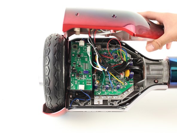
Remove the base plate by lifting it up.
-
-
-
Dieser Schritt ist noch nicht übersetzt. Hilf mit, ihn zu übersetzen!
-
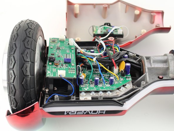
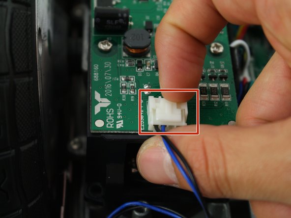
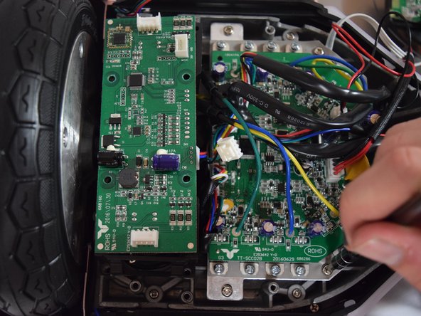
Remove the two connectors on either side of the board by lifting the tab and pulling out.
-
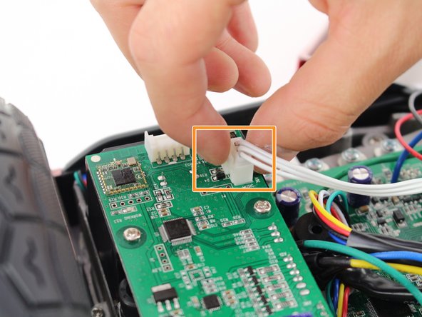
Remove the connector in the middle of the board by squeezing the tab and pulling up.
-
-
Dieser Schritt ist noch nicht übersetzt. Hilf mit, ihn zu übersetzen!
-
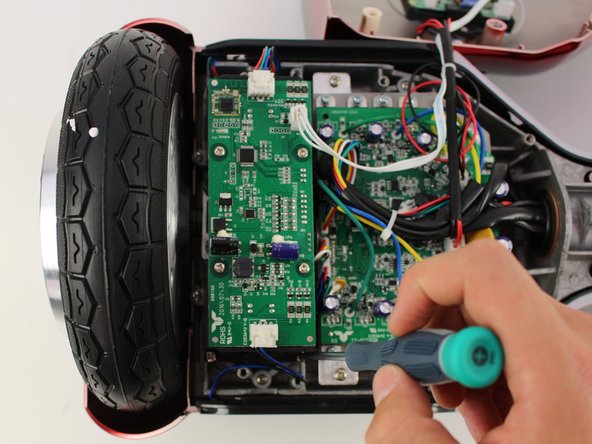
Remove the four 11mm Phillips #1 screws that hold the cover on.
-
-
Dieser Schritt ist noch nicht übersetzt. Hilf mit, ihn zu übersetzen!
-
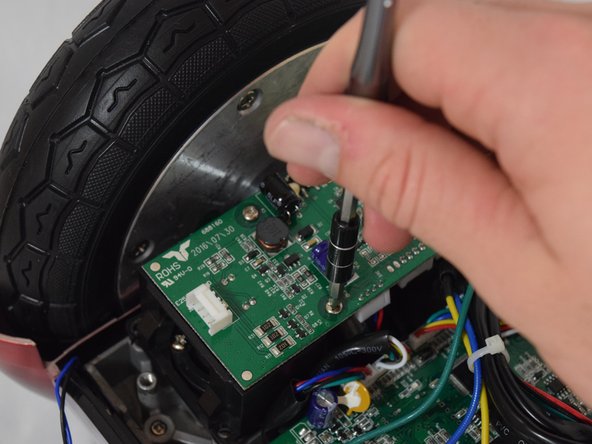
Remove the four 11mm Phillips #1 screws that attach the gyroscope board to the mount.
-
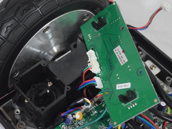
Lift the board to reveal the connections on the bottom.
-
-
Dieser Schritt ist noch nicht übersetzt. Hilf mit, ihn zu übersetzen!
-
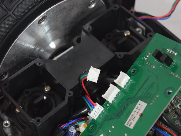
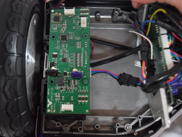
Remove the middle connector by squeezing the top of the tab and pulling up.
-
-
Dieser Schritt ist noch nicht übersetzt. Hilf mit, ihn zu übersetzen!
-
Remove the four 12mm Phillips #2 screws that hold the motherboard to the base.
-
Pull the motherboard away from the gyroscope by grabbing it with two hands and pulling it to the right .
-
-
Dieser Schritt ist noch nicht übersetzt. Hilf mit, ihn zu übersetzen!
-
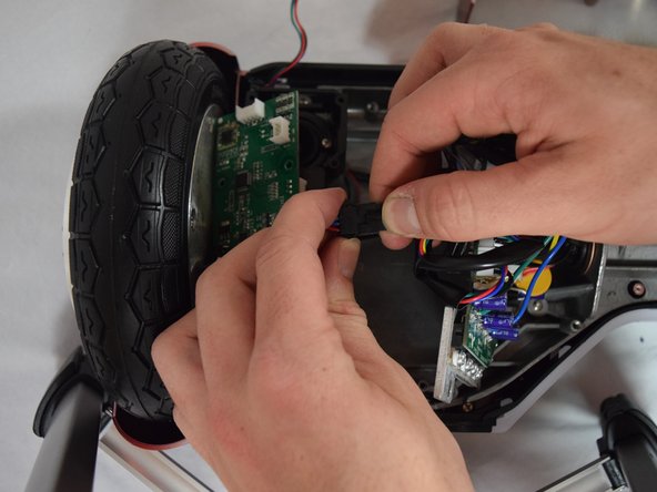
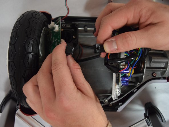
Unclip the black connector by squeezing both sides and pulling them apart.
-


Rückgängig: Ich habe diese Anleitung nicht absolviert.
Ein:e weitere:r Nutzer:in hat diese Anleitung absolviert.
Team

Cal Poly, Team S13-G6, White Fall 2018 Mitglied von Cal Poly, Team S13-G6, White Fall 2018
CPSU-WHITE-F18S13G6
4 Mitglieder
6 Anleitungen geschrieben