Diese Version enthält möglicherweise inkorrekte Änderungen. Wechsle zur letzten geprüften Version.
Was du brauchst
-
-
Ziehe und drehe den Pin links unten am Smartphone, um ihn aus der Kopfhörerbuchse zu entfernen.
-
Huawei Ascend P6
-
-
-
Führe den Pin in das Loch im SIM-Karten Fach ein.
-
Vorsichtig drücken bis die SIM-Karte klickt, dann ziehe den Pin und die SIM-Karte heraus.
-
Wiederhole den Vorgang für das zweite Fach.
-
-
-
Drücke etwas auf die schwarze Plastikabdeckung unten am Smartphone und ziehe sie nach unten.
-
-
-
Drehe das Smartphone um 180°, so dass die Unterseite nach oben zeigt.
-
Drücke die Rückseite mit deinen Daumen kräftig nach oben.
-
Hebe die Rückseite von der oberen rechten Ecke ausgehend an und ziehe sie vorsichtig vom Smartphone weg.
-
-
-
Entferne folgenden Schrauben, die das Logic Board am Rahmen befestigen:
-
Fünf 2 mm Kreuzschlitzschrauben #000
-
Zwei 2,5 mm Kreuzschlitzschrauben #000
To replace the battery only the two orange 2.5mm screws need to be removed in this step.
-
-
-
Drücke die gelbe Plastikauskleidung oben am Akku nach unten und entferne die beiden 2,5mm Kreuzschlitzschrauben #000.
-
-
-
Benutze das flache Ende eines Spudgers, um den ersten Clip an der rechten Abzweigung der Halteplatte vorsichtig aufzudrücken.
-
Benutze das flache Ende eines Spudgers, um den zweiten Clip an der linken Abzweigung der Halteplatte aufzudrücken.
-
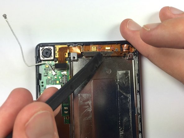
Benutze nun wieder das flache Ende des Spudgers, um vorsichtig die obere Halteplatte vom Smartphone zu heben.
-
-
-
Benutze das spitze Ende eines Spudgers, um das Antennenstecker von seinem Anschluss zu trennen.
-
-
-
-
Benutze das spitze Ende des Spudgers, um vorsichtig folgende Stecker aus ihren Anschlüssen zu hebeln:
-
Silberner LCD Kabel stecken
-
Silberner Kopfhöreranschluss Kabelstecker
-
-
-
Benutze das spitze Ende eines Spudgers, um folgende Stecker vorsichtig aus ihren Anschlüssen zu hebeln:
-
Silberner Micro-USB Kabelstecker
-
Kupferner Akku Kabelstecker
-
-
-
Benutze ein Plastiköffnungswerkzeug, um den Akku vorsichtig vom unteren Ende nach oben zu heben.
-
-
Dieser Schritt ist noch nicht übersetzt. Hilf mit, ihn zu übersetzen!
-
Remove the two 2mm Phillips #000 screws securing the copper flex cable to the silver metal tab.
-
-
Dieser Schritt ist noch nicht übersetzt. Hilf mit, ihn zu übersetzen!
-
Wedge the flat end of a spudger underneath the bottom left of the metal tab.
-
Run the spudger along the bottom edge of the metal tab and gently pry upward.
-
-
Dieser Schritt ist noch nicht übersetzt. Hilf mit, ihn zu übersetzen!
-
Gently lift the flex cable from the top-right corner.
-
-
Dieser Schritt ist noch nicht übersetzt. Hilf mit, ihn zu übersetzen!
-
Use tweezers to lift the rubber alignment tab out of its frame.
-
-
Dieser Schritt ist noch nicht übersetzt. Hilf mit, ihn zu übersetzen!
-
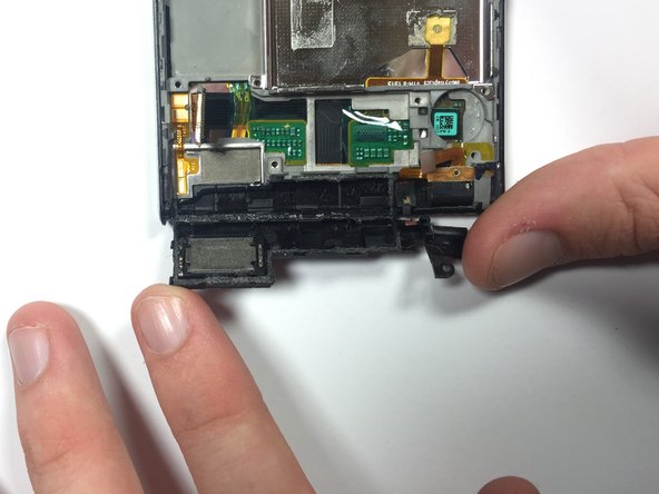
Use the pointy end of a spudger to wedge underneath the black circular vibrator motor near the bottom right of the phone.
-
Slowly lift up to separate the black circular vibrator motor from the adhesive.
-
-
Dieser Schritt ist noch nicht übersetzt. Hilf mit, ihn zu übersetzen!
-
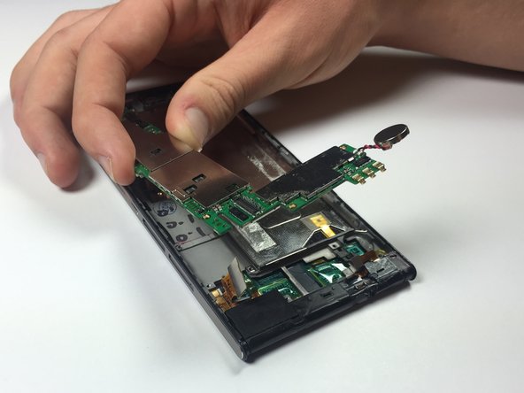
Hold down the bottom left corner of the motherboard and slowly lift the right side out of the main frame.
-
Gently wiggle the logic board to release it from the phone.
-
-
Dieser Schritt ist noch nicht übersetzt. Hilf mit, ihn zu übersetzen!
-
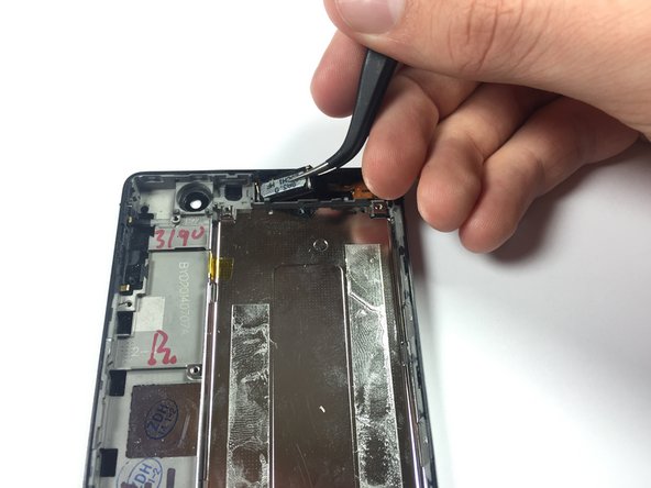
Use the pointy end of a spudger to wedge underneath the earpiece speaker, and gently pry upward.
-
Use tweezers to remove the earpiece speaker from the frame.
-
-
Dieser Schritt ist noch nicht übersetzt. Hilf mit, ihn zu übersetzen!
-
Use the pointy end of a spudger to peel back and fold down the black plastic cover near the bottom left of the phone.
-
-
Dieser Schritt ist noch nicht übersetzt. Hilf mit, ihn zu übersetzen!
-
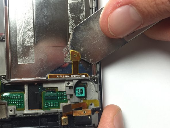
Use an iSesamo tool to separate the gold wire from the silver metal plate.
-
-
Dieser Schritt ist noch nicht übersetzt. Hilf mit, ihn zu übersetzen!
-
Use a heat gun to loosen the adhesive between the display and frame.
-
Start with the heat gun far away from your hand. Then, slowly move your hand towards the heat gun until the air is warm, but not hot.
-
At this set distance, slowly warm the entire front of the phone.
-
-
Dieser Schritt ist noch nicht übersetzt. Hilf mit, ihn zu übersetzen!
-
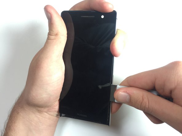
Use the iSeasmo tool to wedge between the screen and the plastic near the bottom right corner of the phone. You must wedge the iSeasmo underneath the white plastic part of the screen, and not just the glass.
-
Run your iSeasmo tool slowly to the left and right to begin separating the display.
-
Run your iSeasmo tool along the right and left edges of the display.
-
-
Dieser Schritt ist noch nicht übersetzt. Hilf mit, ihn zu übersetzen!
-
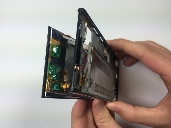
Once the display is loose enough, gently begin separating it from the bottom of the phone. Work your way up until it is completely removed.
-


Rückgängig: Ich habe diese Anleitung nicht absolviert.
18 weitere Nutzer:innen haben diese Anleitung absolviert.
Team

Cal Poly, Team 4-44, Amido Fall 2014 Mitglied von Cal Poly, Team 4-44, Amido Fall 2014
CPSU-AMIDO-F14S4G44
5 Mitglieder
11 Anleitungen geschrieben
5 Kommentare
Where did you buy the replacement screen?
To find the screen you are looking for just do a Google search, and you should no problem getting what you need.
After changing the ear piece, my phone refuse to display after putting it on, what could be wrong.