Diese Version enthält möglicherweise inkorrekte Änderungen. Wechsle zur letzten geprüften Version.
Was du brauchst
-
Dieser Schritt ist noch nicht übersetzt. Hilf mit, ihn zu übersetzen!
-
Flip the stereo so the CD opening is face down.
-
With two fingers, pinch the tabs and lift up to open the battery protection cover.
-
-
Dieser Schritt ist noch nicht übersetzt. Hilf mit, ihn zu übersetzen!
-
Using a spudger or your fingers, push up against the positive end of the battery. Once it is loose, lift the battery out.
-
Repeat until all eight batteries are removed.
-
-
Dieser Schritt ist noch nicht übersetzt. Hilf mit, ihn zu übersetzen!
-
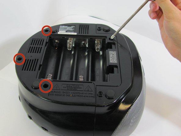
With a Phillips #2 screwdriver, remove two 2mm screws.
-
-
Dieser Schritt ist noch nicht übersetzt. Hilf mit, ihn zu übersetzen!
-
Using a long Phillips #2 screwdriver, remove one 6mm screw located inside the battery compartment.
-
Use the same screwdriver to remove four more 6mm screws along the outside of the case.
-
-
Dieser Schritt ist noch nicht übersetzt. Hilf mit, ihn zu übersetzen!
-
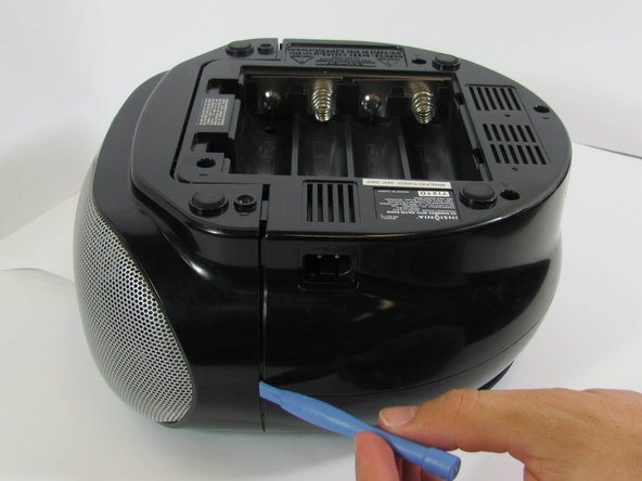
With a plastic opening tool, wedge the bottom shell from the main speaker face along the edge.
-
Once the pieces are separated, pull them apart and place the bottom cover aside, near the stereo.
-
-
Dieser Schritt ist noch nicht übersetzt. Hilf mit, ihn zu übersetzen!
-
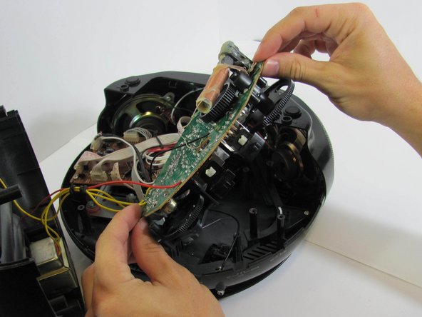
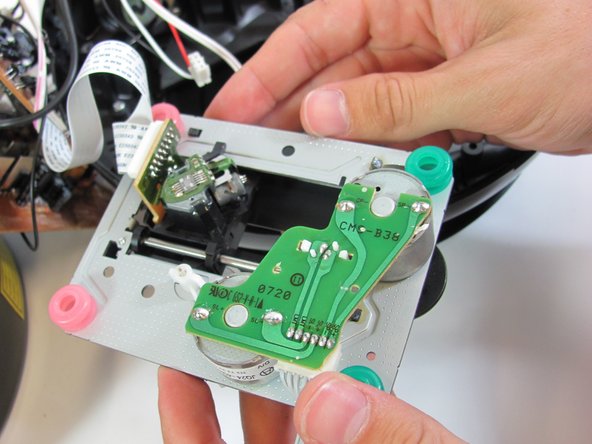
With a Phillips #2 screwdriver, remove five 5mm screws from the "quarter circle" circuit board.
-
Remove the green quarter circle circuit board and place to the side.
-
-
-
Dieser Schritt ist noch nicht übersetzt. Hilf mit, ihn zu übersetzen!
-
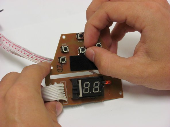
On the brown side of the quarter circle circuit board, remove the two white ribbon cables with pink stripes attached to a plastic connector. To do this, pinch the tabs with your hands while pulling outward on the connector.
-
-
Dieser Schritt ist noch nicht übersetzt. Hilf mit, ihn zu übersetzen!
-
With a Phillips #2 screwdriver, remove four 6mm screws from the rectangular circuit board.
-
-
Dieser Schritt ist noch nicht übersetzt. Hilf mit, ihn zu übersetzen!
-
Remove the two white ribbon cables attached to white plastic connectors from the circuit board by pinching the tabs with your hands and pulling outward on the connector.
-
-
Dieser Schritt ist noch nicht übersetzt. Hilf mit, ihn zu übersetzen!
-
Remove the rectangular circuit board and place it to the side.
-
-
Dieser Schritt ist noch nicht übersetzt. Hilf mit, ihn zu übersetzen!
-
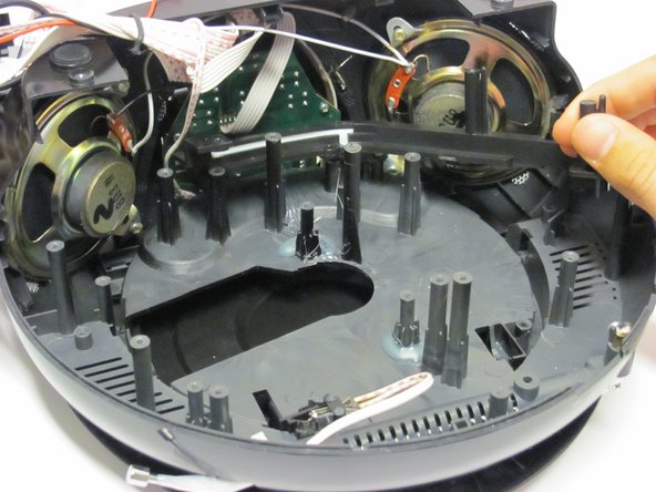
With a Phillips #2 screwdriver, remove two 5mm screws from the black plastic frame which previously held up the rectangular circuit board.
-
Remove the black plastic frame.
-
-
Dieser Schritt ist noch nicht übersetzt. Hilf mit, ihn zu übersetzen!
-
With a Phillips #1 screwdriver, remove four 3mm screws from the silver metal circuit board.
-
Remove and place the metal circuit board to the side.
-
-
Dieser Schritt ist noch nicht übersetzt. Hilf mit, ihn zu übersetzen!
-
With a Phillips #2 screwdriver, remove the two 3mm screws from the black plastic tuner frame.
-
-
Dieser Schritt ist noch nicht übersetzt. Hilf mit, ihn zu übersetzen!
-
Remove the black plastic tuner assembly piece using the blue plastic opening tool.
-
-
Dieser Schritt ist noch nicht übersetzt. Hilf mit, ihn zu übersetzen!
-
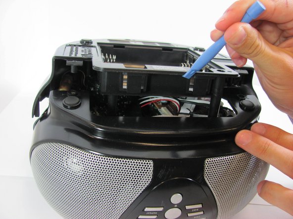
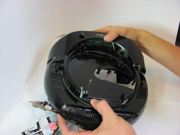
Turn the device so the CD tray faces up.
-
Use the blue plastic opening tool to separate the front half (containing the speakers and display) and the back half (containing the antenna).
-
Pull the two plastic pieces apart. This will require a mild amount of force.
-
-
Dieser Schritt ist noch nicht übersetzt. Hilf mit, ihn zu übersetzen!
-
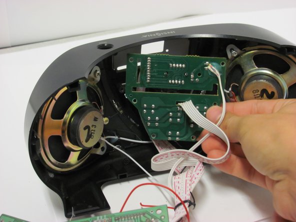
Remove the six 5mm #2 Phillips head screws from the circuit board.
-
Remove the circuit board. This may require you to wiggle the board a little to get it free.
-
-
Dieser Schritt ist noch nicht übersetzt. Hilf mit, ihn zu übersetzen!
-
Remove the solder from the back of the button. There are 4 points of solder for every button.
-
Remove the button from the circuit board.
-


Team

Cal Poly, Team 4-31, Amido Fall 2013 Mitglied von Cal Poly, Team 4-31, Amido Fall 2013
CPSU-AMIDO-F13S4G31
4 Mitglieder
8 Anleitungen geschrieben