Diese Version enthält möglicherweise inkorrekte Änderungen. Wechsle zur letzten geprüften Version.
Was du brauchst
-
Dieser Schritt ist noch nicht übersetzt. Hilf mit, ihn zu übersetzen!
-
Slide the grey plastic cover laterally off the back of the device.
-
-
Dieser Schritt ist noch nicht übersetzt. Hilf mit, ihn zu übersetzen!
-
Use a plastic opening tool to lift the battery on the side closest to the edge of the device.
-
Unplug the battery from the device by pinching the white connector and pulling.
-
-
Dieser Schritt ist noch nicht übersetzt. Hilf mit, ihn zu übersetzen!
-
Unscrew eight (8) Phillips #00 screws (3 mm).
-
-
Dieser Schritt ist noch nicht übersetzt. Hilf mit, ihn zu übersetzen!
-
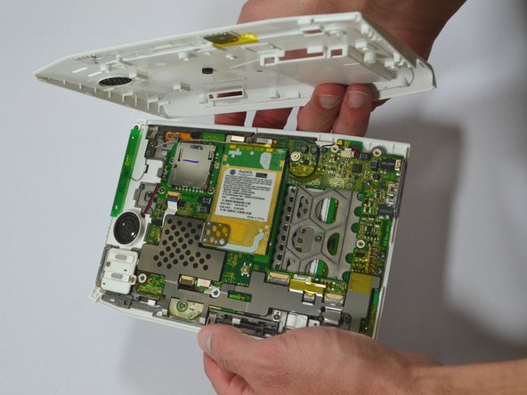
Start at one side of the device. Use a plastic opening tool to separate the casing of the device. Slowly work your way around the entire device.
-
-
Dieser Schritt ist noch nicht übersetzt. Hilf mit, ihn zu übersetzen!
-
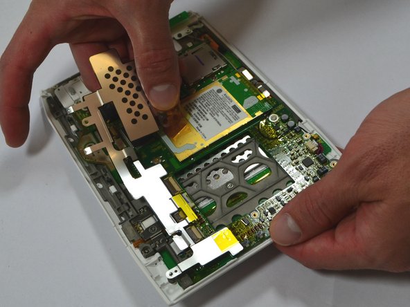
Unscrew the two (2) Phillips #00 screws (3 mm) which fasten the metal casing shield.
-
Slowly remove the metal casing shield by lifting it and carefully peeling up the tape.
-
-
Dieser Schritt ist noch nicht übersetzt. Hilf mit, ihn zu übersetzen!
-
Remove the four (4) Phillips #00 screws (3 mm) which fasten the SD Card Reader.
-
-
Dieser Schritt ist noch nicht übersetzt. Hilf mit, ihn zu übersetzen!
-
Lift the flap attaching the blue and white ribbon cable to the motherboard by lifting it vertically with a spudger.
-
Carefully lift the SD Card Reader vertically from the motherboard.
-
-
-
Dieser Schritt ist noch nicht übersetzt. Hilf mit, ihn zu übersetzen!
-
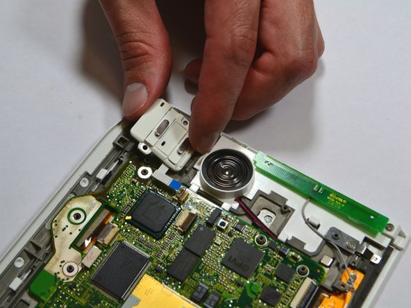
Remove the two (2) Phillips #00 screws (3 mm) connecting the ON/OFF Power and Wifi Switches.
-
-
Dieser Schritt ist noch nicht übersetzt. Hilf mit, ihn zu übersetzen!
-
Lift the flap attaching the blue and white ribbon cable to the motherboard by lifting it vertically with the pointed-end of the spudger.
-
Carefully lift the ON/OFF Power and Wifi Switches vertically from the device motherboard.
-
-
Dieser Schritt ist noch nicht übersetzt. Hilf mit, ihn zu übersetzen!
-
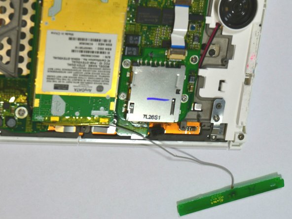
Use a spudger to remove the Wifi antenna from the device by carefully prying it up off the casing.
-
-
Dieser Schritt ist noch nicht übersetzt. Hilf mit, ihn zu übersetzen!
-
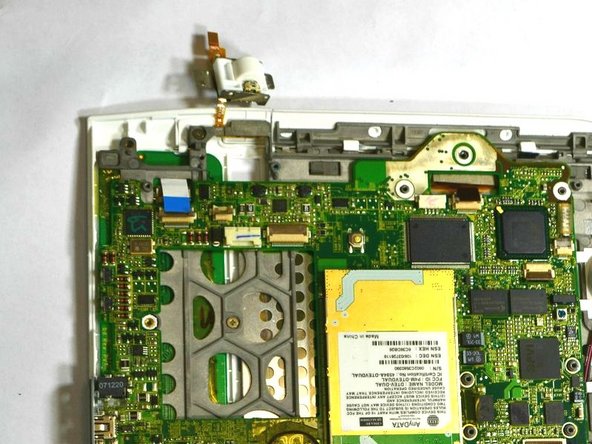
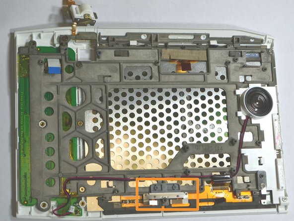
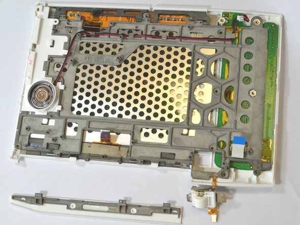
Unscrew the two (2) Phillips #00 screws (3 mm) attaching the scroll bar.
-
Use a spudger to lift the flap vertically in the second image to release the scroll bar from the motherboard.
-
-
Dieser Schritt ist noch nicht übersetzt. Hilf mit, ihn zu übersetzen!
-
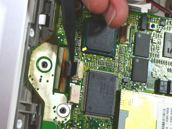
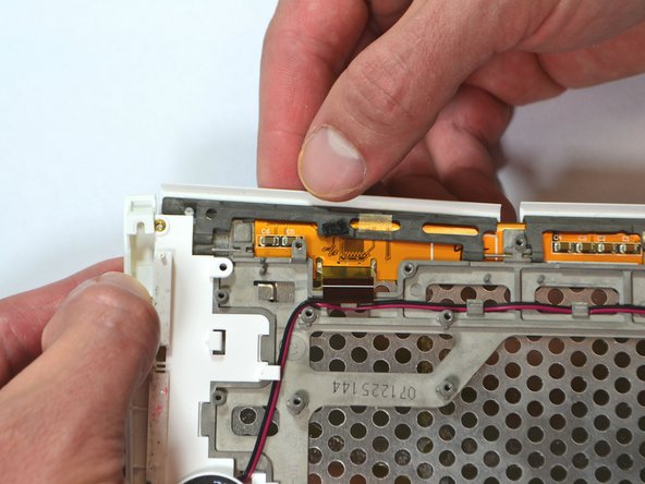
Lift the flap attaching the blue and white ribbon cable to the motherboard by lifting it vertically with the spudger.
-
Lift the flap with the pointed-end of the spudger to detach the ribbon cable indicated in the second image.
-
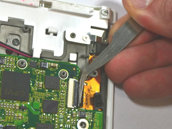
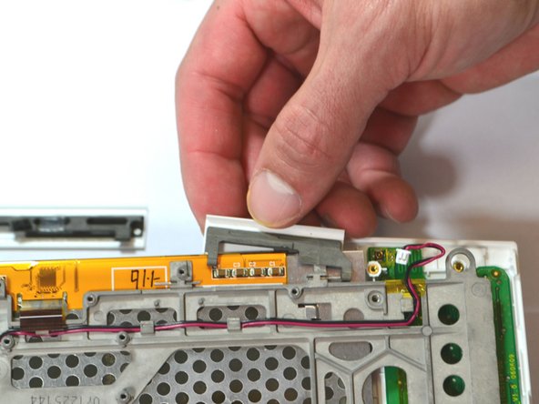
Use tweezers to pull the ribbon cable in the third image laterally to detach it.
-
-
Dieser Schritt ist noch nicht übersetzt. Hilf mit, ihn zu übersetzen!
-
Detach the cable by pulling laterally with tweezers or your fingertips. Do this by grasping the edges of the white connector and pulling laterally.
-
Grasp the end of the cable with tweezers or your fingertips and pull upwards to detach it from the motherboard.
-
-
Dieser Schritt ist noch nicht übersetzt. Hilf mit, ihn zu übersetzen!
-
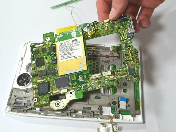
Remove the two (2) Phillips #00 screws (3 mm) which attach the motherboard to the front casing.
-
Carefully lift the motherboard off.
-
The piece marked in the third image may be loose and fall out freely. If it does not fall off, use your fingers or a plastic opening tool to snap it off. Make sure to place it under the motherboard during reassembly, as found in the image.
-
-
Dieser Schritt ist noch nicht übersetzt. Hilf mit, ihn zu übersetzen!
-
Remove the seven (7) Phillips #00 screws (3 mm) remaining on the frame.
-
-
Dieser Schritt ist noch nicht übersetzt. Hilf mit, ihn zu übersetzen!
-
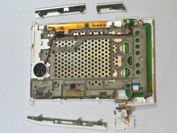
Press down firmly on the two white tabs, behind the large 'NEXT PAGE' button with the spudger. This will unsnap the front casing from the rest of the device.
-
Slide out the large 'NEXT PAGE' button laterally away from the keyboard.
-
-
Dieser Schritt ist noch nicht übersetzt. Hilf mit, ihn zu übersetzen!
-
Slightly lift the top corner of the panel.
-
Slide the 'PREV PAGE' button out laterally towards the top corner.
-
-
Dieser Schritt ist noch nicht übersetzt. Hilf mit, ihn zu übersetzen!
-
Slide out the small 'NEXT PAGE' button laterally towards the keyboard.
-
-
Dieser Schritt ist noch nicht übersetzt. Hilf mit, ihn zu übersetzen!
-
Slide out the small 'BACK' button laterally towards the keyboard.
-


Team

University of Kentucky Louisville, Team 1-1, Chamberlain Spring 2013 Mitglied von University of Kentucky Louisville, Team 1-1, Chamberlain Spring 2013
LOUISVILLE-CHAMBERLAIN-S13S1G1
2 Mitglieder
7 Anleitungen geschrieben