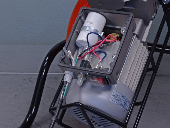
Zum Hauptinhalt wechseln

Kushlan Cement Mixer 600DDS 2014 Power Components Replacement

Was du brauchst

  1. Kushlan Cement Mixer 600DDS 2014 Power Components Replacement, Remove the motor cover bolts: Schritt 1, Bild 1 von 1
    • Before you begin, ensure the power cord is unplugged and the power switch is in the OFF position.

    • Use a 13 mm socket to remove the two bolts securing the motor cover to the frame.

  2. Kushlan Cement Mixer 600DDS 2014 Power Components Replacement, Remove the motor cover: Schritt 2, Bild 1 von 1
    • Remove the motor cover.

  3. Kushlan Cement Mixer 600DDS 2014 Power Components Replacement, Remove the electrical panel: Schritt 3, Bild 1 von 1
    • Use a Phillips screwdriver to remove the four screws securing the electrical panel.

  4. Kushlan Cement Mixer 600DDS 2014 Power Components Replacement, Remove the electrical panel: Schritt 4, Bild 1 von 1
    • Remove the electrical panel.

  5. Kushlan Cement Mixer 600DDS 2014 Power Components Replacement, Remove the on/off switch: Schritt 5, Bild 1 von 3 Kushlan Cement Mixer 600DDS 2014 Power Components Replacement, Remove the on/off switch: Schritt 5, Bild 2 von 3 Kushlan Cement Mixer 600DDS 2014 Power Components Replacement, Remove the on/off switch: Schritt 5, Bild 3 von 3
    • Use a pair of needle-nose pliers to disconnect the four wires from the back of the on/off switch.

    • During reassembly, ensure the wires are connected back into their original locations and the on/off switch is not upside-down.

  6. Kushlan Cement Mixer 600DDS 2014 Power Components Replacement: Schritt 6, Bild 1 von 3 Kushlan Cement Mixer 600DDS 2014 Power Components Replacement: Schritt 6, Bild 2 von 3 Kushlan Cement Mixer 600DDS 2014 Power Components Replacement: Schritt 6, Bild 3 von 3
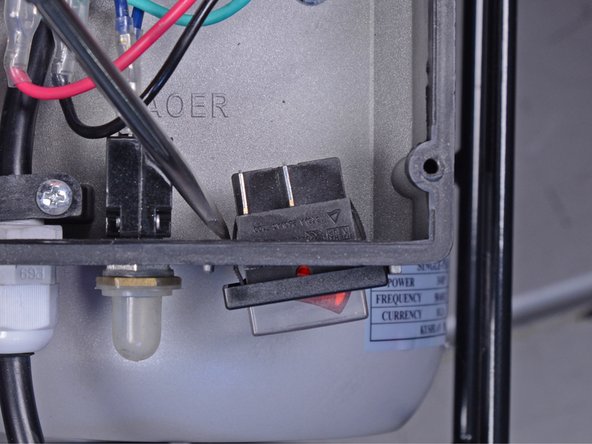
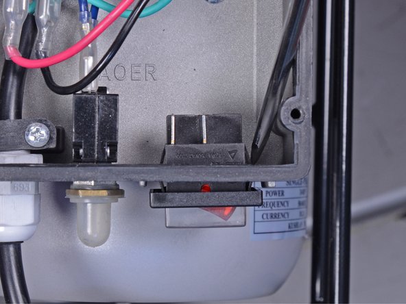
    • Use a flathead screwdriver to press the sides of the on/off switch through the opening in the electrical box.

  7. Kushlan Cement Mixer 600DDS 2014 Power Components Replacement: Schritt 7, Bild 1 von 1
    • Remove the on/off switch.

  8. Kushlan Cement Mixer 600DDS 2014 Power Components Replacement, Remove the power cord: Schritt 8, Bild 1 von 1
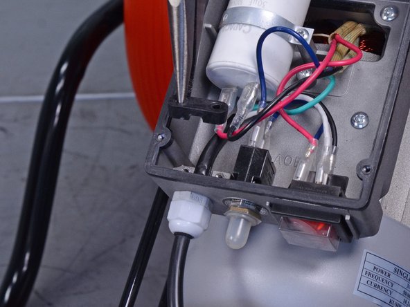
    • Use a Phillips screwdriver to remove the two screws securing the fastener behind the strain relief fitting.

  9. Kushlan Cement Mixer 600DDS 2014 Power Components Replacement: Schritt 9, Bild 1 von 2 Kushlan Cement Mixer 600DDS 2014 Power Components Replacement: Schritt 9, Bild 2 von 2
    • Remove the fastener.

  10. Kushlan Cement Mixer 600DDS 2014 Power Components Replacement: Schritt 10, Bild 1 von 1
    • Use a Phillips screwdriver to remove the screw securing the green ground wire to the bottom of the electrical box.

  11. Kushlan Cement Mixer 600DDS 2014 Power Components Replacement: Schritt 11, Bild 1 von 1
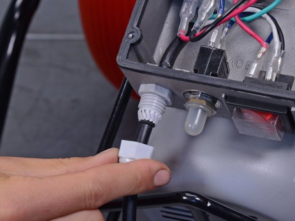
    • Use an adjustable wrench to remove the power cord's strain relief fitting cap.

  12. Kushlan Cement Mixer 600DDS 2014 Power Components Replacement: Schritt 12, Bild 1 von 2 Kushlan Cement Mixer 600DDS 2014 Power Components Replacement: Schritt 12, Bild 2 von 2
    • Slide the cap off of the strain relief fitting.

  13. Kushlan Cement Mixer 600DDS 2014 Power Components Replacement: Schritt 13, Bild 1 von 3 Kushlan Cement Mixer 600DDS 2014 Power Components Replacement: Schritt 13, Bild 2 von 3 Kushlan Cement Mixer 600DDS 2014 Power Components Replacement: Schritt 13, Bild 3 von 3
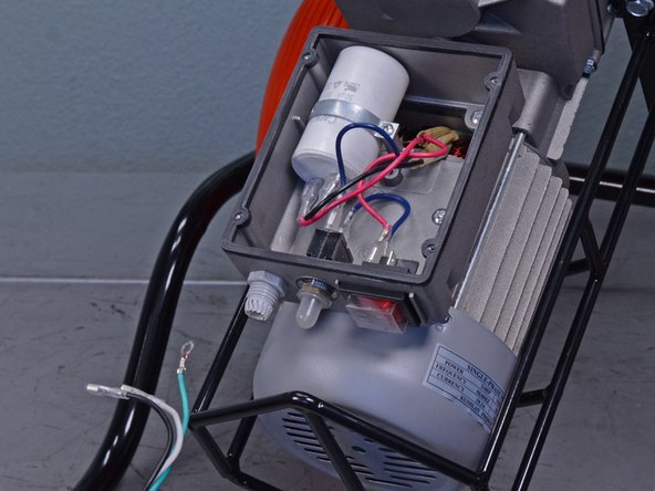
    • Feed the power cord and its black, white, and green wires out through the strain relief fitting.

    • Transfer the strain relief fitting cap onto the new power cord.

  14. Kushlan Cement Mixer 600DDS 2014 Power Components Replacement, Remove the capacitor: Schritt 14, Bild 1 von 1
    • Use a Phillips screwdriver to remove the screw securing the capacitor support.

  15. Kushlan Cement Mixer 600DDS 2014 Power Components Replacement: Schritt 15, Bild 1 von 1
    • Remove the capacitor support.

  16. Kushlan Cement Mixer 600DDS 2014 Power Components Replacement: Schritt 16, Bild 1 von 3 Kushlan Cement Mixer 600DDS 2014 Power Components Replacement: Schritt 16, Bild 2 von 3 Kushlan Cement Mixer 600DDS 2014 Power Components Replacement: Schritt 16, Bild 3 von 3
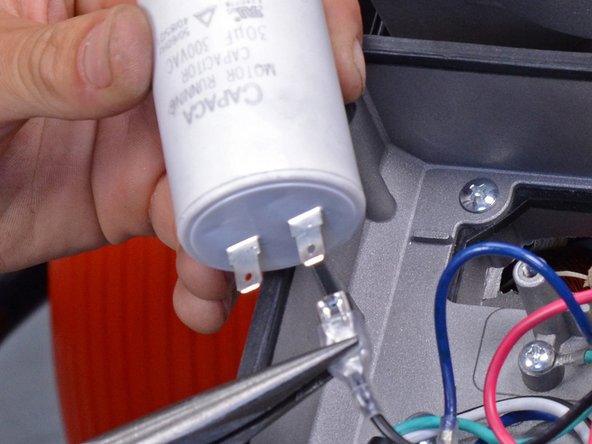
    • Use a pair of needle nose pliers to disconnect the red and black wires from the capacitor.

    • Remove the capacitor.

    • Use tape or a zip tie to differentiate this set of red and white wires from the other set of red and white wires running to the on/off switch to ensure proper reinstallation.

Abschluss

To reassemble your device, follow these instructions in reverse order.

5 weitere Nutzer:innen haben diese Anleitung absolviert.

Sam Omiotek

Mitglied seit: 02/25/19

73.429 Reputation

288 Anleitungen geschrieben

0 Kommentare

Kommentar hinzufügen

Seitenaufrufe:

Letzte 24 Stunden: 0

Letzte 7 Tage: 18

Letzte 30 Tage: 111

Insgesamt: 2,552