Einleitung
Faulty power ports can result in loss of power to your device. This guide will show you how to identify and replace a dysfunctional power port on your router.
Make sure you are in a well ventilated area at room temperature with the proper safety equipment when soldering.
Was du brauchst
-
-
Remove the antennas by unscrewing them from the base.
-
Flip over the device and locate the four rubber feet on the bottom.
-
Remove the rubber feet with tweezers
-
-
-
Remove the 0.4cm head screws from each slot with the #1 Phillips head Screwdriver.
-
-
-
-
Use a blue plastic opening tool to remove the top cover.
-
Move the blue plastic opening tool gently underneath the top cover from side to side.
-
-
-
Gently lift the motherboard and remove it from the case
-
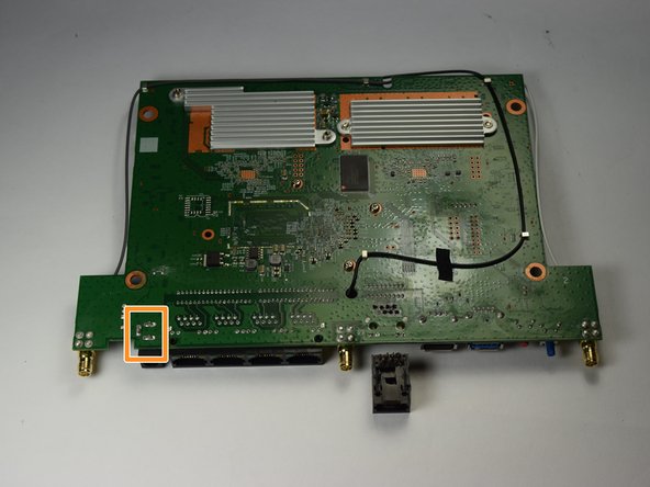
Put the motherboard over a (preferably white) surface.
-
-
-
Locate the power port on both sides of the motherboard.
-
The power port on the top side is in a rectangular black casing.
-
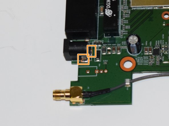
Identify the three prongs where the power port is soldered to on the reverse side.
-
-
-
Carefully apply the soldering iron on each of the three points on the bottom side of the motherboard to melt them.
-
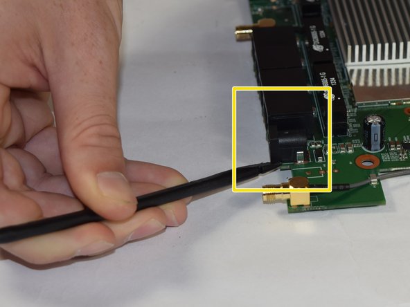
After you have melted and removed the solder, flip the mother board around and identify the connecting points of the power port.
-
Use a black spudger to gently separate the power port from the motherboard
-


To reassemble your device, follow these instructions in reverse order.
To reassemble your device, follow these instructions in reverse order.
Rückgängig: Ich habe diese Anleitung nicht absolviert.
2 weitere Personen haben diese Anleitung absolviert.
Team

USF Tampa, Team 11-1, Blackwell Fall 2016 Mitglied von USF Tampa, Team 11-1, Blackwell Fall 2016
USFT-BLACKWELL-F16S11G1
4 Mitglieder
12 Anleitungen geschrieben