Diese Version enthält möglicherweise inkorrekte Änderungen. Wechsle zur letzten geprüften Version.
Was du brauchst
-
KaufenIn diesem Schritt verwendetes Werkzeug:P5 Pentalobe Screwdriver Retina MacBook Pro and Air$5.99
-
Entferne die folgenden zehn Schrauben:
-
Zwei 8 mm 5-Point Pentalobe Schrauben
-
Acht 2,5 mm 5-Point Pentalobe Schrauben
-
-
-
Löse das Gehäuseunterteil vom Air, indem du mit den Fingerspitzen zwischen Display und Gehäuse gehst und es nach oben ziehst.
-
Entferne das Gehäuseunterteil und lege es beiseite.
-
-
Dieser Schritt ist noch nicht übersetzt. Hilf mit, ihn zu übersetzen!
-
Use the flat end of a spudger to pry both short sides of the battery connector upward to disconnect it from its socket on the logic board.
-
Bend the battery cable slightly away from the logic board so the connector will not accidentally contact its socket.
-
-
Dieser Schritt ist noch nicht übersetzt. Hilf mit, ihn zu übersetzen!
-
Remove the single 2.9 mm T5 Torx screw securing the SSD to the logic board.
-
-
Dieser Schritt ist noch nicht übersetzt. Hilf mit, ihn zu übersetzen!
-
Use a spudger to help lift the free end of the SSD just enough to grab it with your other hand.
-
Pull the drive straight out of its socket and remove it from the logic board.
-
-
Dieser Schritt ist noch nicht übersetzt. Hilf mit, ihn zu übersetzen!
-
Use the flat end of a spudger to pry the I/O board cable connector upward out of its socket on the I/O board.
-
-
Dieser Schritt ist noch nicht übersetzt. Hilf mit, ihn zu übersetzen!
-
While gently pulling the I/O board cable upward near its connection to the logic board, use the tip of a spudger to pry upward on alternating sides of the connector to help "walk" it out of its socket.
-
Remove the I/O board cable.
-
-
-
Dieser Schritt ist noch nicht übersetzt. Hilf mit, ihn zu übersetzen!
-
Use the tip of a spudger to carefully flip up the retaining flap on the fan cable ZIF socket.
-
-
Dieser Schritt ist noch nicht übersetzt. Hilf mit, ihn zu übersetzen!
-
Remove the following three screws securing the fan to the upper case:
-
Two 5.2 mm T5 Torx screws
-
One 3.6 mm T5 Torx screw
-
-
Dieser Schritt ist noch nicht übersetzt. Hilf mit, ihn zu übersetzen!
-
Lift the fan out of the upper case and carefully pull the fan ribbon cable out of its socket as you remove it from the Air.
-
-
Dieser Schritt ist noch nicht übersetzt. Hilf mit, ihn zu übersetzen!
-
Remove the following five screws securing the battery to the upper case:
-
Two 5.2 mm T5 Torx screws
-
One 6 mm T5 Torx screw
-
Two 2.6 mm T5 Torx screws
-
-
Dieser Schritt ist noch nicht übersetzt. Hilf mit, ihn zu übersetzen!
-
Lift the battery from its edge nearest the logic board and remove it from the upper case.
-
-
Dieser Schritt ist noch nicht übersetzt. Hilf mit, ihn zu übersetzen!
-
Disconnect the I/O board by pulling the power cable away from its socket on the logic board.
-
-
Dieser Schritt ist noch nicht übersetzt. Hilf mit, ihn zu übersetzen!
-
Use the tip of a spudger to carefully flip up the retaining flap on the microphone cable ZIF socket.
-
Pull the microphone ribbon cable straight out of its socket.
-
-
Dieser Schritt ist noch nicht übersetzt. Hilf mit, ihn zu übersetzen!
-
Use the flat end of a spudger to pry the left speaker cable connector up and out of its socket on the I/O board.
-
-
Dieser Schritt ist noch nicht übersetzt. Hilf mit, ihn zu übersetzen!
-
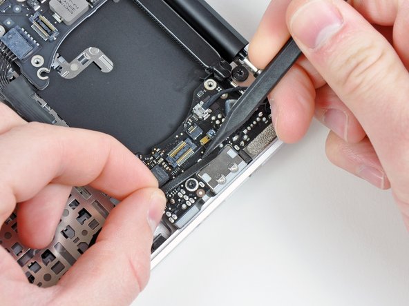
Pull the camera cable parallel to the face of the I/O board toward the rear edge of the Air to disconnect it from its socket.
-
-
Dieser Schritt ist noch nicht übersetzt. Hilf mit, ihn zu übersetzen!
-
Remove the small rubber gasket from the corner of the upper case nearest the I/O board.
-
-
Dieser Schritt ist noch nicht übersetzt. Hilf mit, ihn zu übersetzen!
-
Remove the single 3.6 mm T5 Torx screw securing the I/O board to the upper case.
-
-
Dieser Schritt ist noch nicht übersetzt. Hilf mit, ihn zu übersetzen!
-
Carefully lift the I/O board from its edge nearest the logic board and remove it from the upper case.
-


Rückgängig: Ich habe diese Anleitung nicht absolviert.
15 weitere Nutzer:innen haben diese Anleitung absolviert.

Ein Kommentar
Question. Im looking a replacing the I/O board on my MacBook air and am wondering if it matters whether I get the board for the 13” or the 11”? Are the two boards different? It seems that the 11” I/O board is cheaper so I just trying to figure out if it matters which one I get?