Einleitung
Hier wird der Austausch eines defekten Logic Boards gezeigt.
Was du brauchst
-
-
Entferne folgende Schrauben:
-
Zwei 8mm 5-point Pentalobe Schrauben
-
Acht 2,5 mm 5-point Pentalobe Schrauben
-
-
-
Zwänge deine Finger zwischen Display und Gehäuseunterteil und ziehe nach oben, damit es sich vom Air löst.
-
-
-
Hebele mit dem flachen Ende eines Spudgers die beiden kurzen Seiten des Akkusteckers nach oben, um ihn von seinem Anschluss auf dem Logic Board zu lösen.
-
Biege das Akkukabel etwas weg vom Logic Board, so dass sich der Stecker nicht wieder versehentlich mit dem Anschluss verbinden kann.
My macbook air's configuration (Mid-2011 core i5) has a different battery connector. It slides into a receptacle on the logic board. If your battery connector does not look like the one pictured, use the pointy end of a spudger to depress the small indentation in the middle of the battery connector cable terminal, and pull aft to release the clasp mechanism.
Maybe your battery connector doesn't match the picture because these instructions are for the mid-2012 model and yours is mid-2011.
-
-
-
Entferne die einzelne 2,9 mm Torx T5 Schraube, welche die SSD am Logic Board befestigt.
-
-
-
Hebe die SSD vorsichtig an dem freien Ende mit dem Spudger hoch, und zwar gerade nur soweit, dass du sie mit der anderen Hand fassen kannst.
-
Ziehe das Laufwerk aus seinem Anschluss und entferne es vom Logic Board.
When you've completed all these steps to replace your SSD, don't despair if the MacBook Air shows a flashing folder with a question mark when you first power up the MacBook Air.
- Power off the machine, then keep the option key (= Alt key) pressed down, power on the machine again, and keep the option key pressed down until a prompt appears.
- If you've set a firmware password, then type it in at the prompt
- You should now be prompted for a hard drive to boot from. Select "EFI Boot"
- The MacBook Air should now boot to a window showing "OS X Utilities"
- Click on the at the top left, then select "Startup Disk..."
- Select your SDD/Hard drive, and restart.
When replacing the SSD, be careful about the connector orientation. Replacement boards look almost the same if they are upside-down. Note that the connector is not reversible - there is a notch that will only line up if the board is right-side up. If it doesn't seem to line up, flip the board over.
can i ask some links for some ssd’s that are compatible with that macbook model ?
Hi I completed steps above, but the MacBook Air 2012 doesn’t seem to read the drive, on reboot I get a flashing folder, and upon clicking Control R on reboot it goes to internet recovery mode and then can’t find the drive on disk utility. Any help would be much appreciated! Thanks, Devin
if you’re using an M2 adaptor, be mindful to check the compatibility with the other end. In my specific case my adaptor was only compatible with M2 Sata and not with M2 NVMe.
This was a confusing upgrade. Sintech M.2 NGFF SSD fo 2010-2011 MacBook Air was used, yet it’s got a graphic in the sales content that claims it works with ‘M’ key only (NVMe, AHCI), so NOT SATA. Yet in the answered questions on Amazon the sales tech claims you MUST use SATA drive. I bought 2 NVMe SSD’s and found that the first USB adapter board was unstable with both. So, bought another adapter board that supported SATA and NVMe (RIITOP M.2 SSD to USB 3.1 adapter that claimed to be compatible with ‘M’ and ‘B+M’ SATA SSD’s) and a SATA SSD (Silicon Power A55 M.2 SATA III). The NVMe drives couldn’t be seen by the MacBook Air, but the SATA drive worked (Restore didn’t work, but SuperDuper! does fine). Physical install is as shown.
-
-
-
Heble den Stecker des I/O Board Kabels mit einem Spudger aus seinem Anschluss auf dem I/O Board.
-
-
-
Löse das I/O Board Kabel vorsichtig von dem Kleber ab, mit dem es am Lüfter festgeklebt ist.
I did not peel the I/O board connector, it is not needed to be peeled away securing it to the fan.
-
-
-
Hebe den I/O Board Stecker mit dem flachen Ende des Spudgers hoch und aus seinem Anschluss auf dem Logic Board.
-
Entferne das I/O Board Kabel.
-
-
-
Klappe mit der Spudgerspitze vorsichtig den Sicherungsbügel am ZIF-Anschluss des Lüfterkabels hoch.
Das ging leider nicht wie beschrieben: an der Mutter links unten war eine Platine befestigt, die über den beschriebenen Sicherungsbügel ragt, so dass der nicht erreichbar war. Ohne zu wissen, ob diese Platine einfach abgeschraubt werden kann, habe ich das lieber gelassen.
-
-
-
Entferne folgende drei Torx T5 Schrauben, welche den Lüfter am oberen Gehäuse befestigen:
-
Zwei 5,2 mm Schrauben
-
Eine 3,6 mm Schraube
-
-
-
-
Hebe den Lüfter aus dem oberen Gehäuse und ziehe vorsichtig das Flachbandkabel zum Lüfter aus seinem Anschluss, während du ihn aus dem Air entfernst.
The replacement fan's ribbon cable is a few mm longer than the original. I t will loop upwards a bit after mounting. The rubber lip on top of the old fan needs to be transferred to the new fan.
-
-
-
Entferne folgende fünf Torx T5 Schrauben, die den Akku am oberen Gehäuse befestigen:
-
Zwei 5,2 mm Schrauben
-
Eine 6 mm Schraube
-
Zwei 2,6 mm Schrauben
-
-
-
Hebe den Akku an der Kante an, die dem Logic Board am nächsten ist, und entferne ihn aus dem Gehäuse.
-
-
-
Das Versorgungskabel der I/O Karte ist mit einer Schleife aus Klebeband am oberen Gehäuse befstigt. Löse sie mit dem flachen Ende des Spudgers.
-
Trenne das I/O Board ab, indem du seinen Stecker aus dem Anschluss auf dem Logic Board ziehst.
-
-
-
Klappe den Sicherungsbügel am ZIF Anschluss des Flachbandkabels der Tastaturbeleuchtung mit der Spudgerspitze hoch.
-
Ziehe das Flachbandkabel der Tastaturbeleuchtung aus seinem Anschluss heraus.
-
-
-
Klappe den Sicherungsbügel am ZIF Anschluss des Flachbandkabels zum Trackpad mit der Spudgerspitze oder deinem Fingernagel hoch.
-
Ziehe das Flachbandkabel zum Trackpad gerade aus seinem Anschluss in Richtung der Vorderkante des Air.
-
-
-
Hole das rechte Lautsprecherkabel mit der Spudgerspitze aus dem Ausschnitt im Logic Board.
-
-
-
Hebele den Stecker am rechten Lautsprecherkabel mit dem flachen Ende des Spudgers hoch und aus seinem Anschluss auf dem Logic Board.
-
-
-
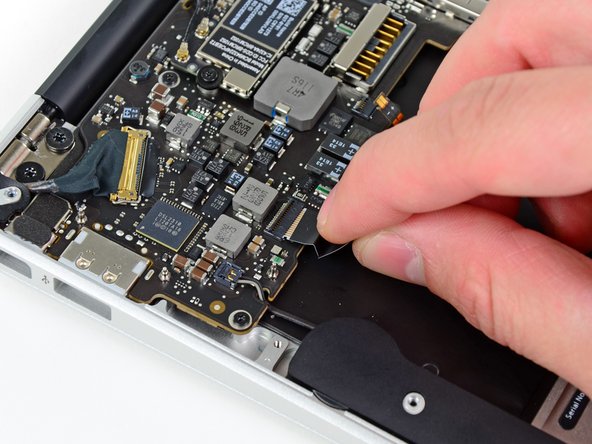
Schiebe vorsichtig einen Spudger unter die schwarze Plastikklappe, die am Sicherungsbügel des Displaydatenkabels befestigt ist, und lasse sie nach oben aufklappen, weg vom Anschluss.
-
Entferne die kleine Gummidichtung in der Ecke des oberen Gehäuses nahe dem Displaydatenkabel.
-
-
-
Halte den Sicherungsbügel weg vom Anschluss und ziehe vorsichtig das Displaydatenkabel aus seinem Anschluss heraus.
-
-
-
Heble beide Antennenstecker mit dem flachen Ende des Spudgers aus ihren Anschlüssen auf der AirPort/Bluetooth Karte hoch.
I'm having difficulty getting the antenna connectors to snap back on. Any suggestions?
-
-
-
Entferne die drei 3,6 mm Torx T5 Schrauben, welche das Logic Board am oberen Gehäuse befestigen.
-
-
-
Hebe die Logic Board Einheit vorsichtig aus dem oberen Gehäuse, achte dabei auf den empfindlichen Kühlkörper und darauf,dass sich keine Kabel verfangen.
-
-
-
Entferne die einzelne 2,9 mm Torx T5 Schraube, welche die AirPort/Bluetooth Karte am Logic Board befestigt.
-
-
-
Hebe das freie Ende der AirPort/Bluetooth Karte etwas hoch und ziehe sie aus ihrem Anschluss auf dem Logic Board.
-
Entferne die AirPort/Bluetooth Karte vom Logic Board.
-
-
-
Entferne die vier 2,5 mm Torx T5 Schrauben, welche den Kühlkörper am Logic Board befestigen.
-
-
-
Entferne den Kühlkörper vom Logic Board.
-
Das Logic Board bleibt zurück.
Be careful if you are running High Sierra and have converted your SSD to the new file system. I replaced my logic board after updating to High Sierra and converting my SSD. The new board would not recognize the drive. I restored the system from a Sierra backup image and all is fine. My assumption is that the High SIerra update includes firmware changes to support the new file system.
-


Um dein Gerät wieder zusammenzusetzen, folge den Schritten in umgekehrter Reihenfolge.
Um dein Gerät wieder zusammenzusetzen, folge den Schritten in umgekehrter Reihenfolge.
Rückgängig: Ich habe diese Anleitung nicht absolviert.
26 weitere Nutzer:innen haben diese Anleitung absolviert.
Besonderer Dank geht an diese Übersetzer:innen:
100%

Diese Übersetzer:innen helfen uns, die Welt zu reparieren! Wie kann ich mithelfen?
Hier starten ›

2 Kommentare
I concur this does not match the A1465 board in some areas. The Airport / Bluetooth connectors are in a different spot and the heatsink is different. Perhaps some photos from another board were used in a few places. The rest appears to be the same, so far.
When you say:
Remove the following ten screws:
Two 8 mm 5-point Pentalobe screws
Eight 2.5 mm 5-point Pentalobe screws
Do the 8mm & 2.5mm dimensions refer to the LENGTH of those screws, or the size of the pentalobe? That is, are there other sizes of pentalobe drivers like there are for hex, phillips and torx? When only one dimension is provided, it is usually the socket/driver size, not the screw length, maybe since the length cannot be seen when the screw is installed.
Can I suggest that you clarify your instructions so folks are confident they are only in need of _one_ pentalobe driver?
Nerdily yours,
Larry (whose iPhone 4S can now get through a day without 6 recharges thanks to ifixit.com ;-)
larryleveen - Antwort
The 8mm and 2.5mm are the length of the screws. One pentalobe P5 screwdriver suffices for all the screws (P5 is implicitly the size of the pentalobe screw heads).
Michael Welham -
I sourced all the parts from ifixit, plus a magnetic project mat which I found to be very useful for organising the teardown and reassembly.
Allen - Antwort
The magnetic mat is
GERARD SZAREK -
Keep the 2.5mm tiny screws away from the MagSafe connector as they will be attracted and sucked in to the magnet.
Frank O'Carroll - Antwort
A tip an old bench tech taught me that has saved me many times: I put clear “Scotch” tape over the case screws as they became “free”. The tape kept them in place while I lifted the lid off, cleaned it etc.
Michael Mee - Antwort
Thank you for a really smart tip! I will be using that countless more times!
Lilljedahl -
I’m confused about internet recovery and installing MacOS. Is all of this done before placing in the new ssd card or after. I don’t have any files that I would like to safe/transfer, is all of this necessary, if I don’t do it before placing new ssd, will I still be able to instal/upgrade macOS afterwards.
It’s an old Mac and now it won’t start or charge, I know I will have to replace battery and put new battery first and turn on Mac before doing the ssd stuff. Since it won’t effing start.
I’m really clueless about backing up old ssd, since I don’t need any files, besides MacOS(software) ,and is that related to the ssd?
AMG - Antwort
The answer to your question: You need to insert your SSD into the computer before internet recovery. If you start the recovery before inserting SSD, it won’t affect the setup, you won’t damage anything. But your SSD will not be detected (as there isn’t one inserted.)
Also, a little tip: If you bought a used SSD, go into Disk Utility and format the drive with the highest security level to permanently remove all of the previous files.
Also a FYI: Internet Recovery will load up Mac OS X 10.9.5 Mavericks, so I would recommend making a recovery drive from a Big Sur (or desired version) through another Mac, and a USB. You can visit this support doc: https://support.apple.com/en-us/HT201372
Hope this helps! -Dan
danielwen -
I got a macbook air with a damaged and swollen battery. I could remove all screws, except one 2,5 mm screw. I’m afraid it got damaged while attempting to remove it, I have no grip with the P5 pentalobe screwdriver. How can I proceed?
Robert Hermans - Antwort
Hi Robert!
Try some techniques found in this stripped screw removal guide. Good luck!
Arthur Shi -
Hello I have a macbook air they are say they do not have parts for my laptop macbook air 11 inches 2013 mid need to replace battery which one to buy
vensilver - Antwort
Hello! This is the part you want—maybe we’re not able to ship it to you if you’re out of the United States. The battery in your MacBook Air should be the same for all 11” between mid-2011 to early-2015.
Arthur Shi -
The smaller screws went in more easily when I put back all the screws along the hinge edge first.
Rachel Slatkin - Antwort