Einleitung
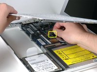
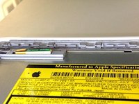
The frame over your ports.
Was du brauchst
-
-
Use a coin or spudger to rotate the battery-locking screw 90 degrees clockwise.
-
-
-
Unscrew the three evenly-spaced Phillips screws from along the rear wall of the battery compartment.
-
-
-
Grasp the right end of the L-shaped memory cover, then pull it towards you so it clears the battery compartment opening.
-
Lift the memory cover up and out of the computer.
-
-
-
Remove the following 3 screws:
-
One 11 mm Phillips#00 in the middle of the lower case. (Head: 5mm dia. x .75mm thick)
-
Two 14.5 mm Phillips #00 (Head: 5mm dia. x .75mm thick)
-
-
-
Remove the following 3 screws from the rear wall of the battery compartment:
-
One 3 mm Phillips #0. (Head: 2.75 mm. dia.)
-
Two 4 mm Phillips #0 on the either side. (Head: 2.75mm dia.)
-
-
-
-
Remove the two Phillips screws from either side of the right wall of the battery compartment (not the ones closest to the battery connector).
-
Two 6.25 mm Phillips #000. (Head: 4 mm. dia. x .5mm thick)
-
-
-
Remove the four indicated Phillips screws from the front wall of the battery compartment. When working from the left, remove the 2nd, 4th, 7th and 9th screws.
-
Four 3.25 mm Phillips #000. (Head: 4 mm. dia. x 4mm thick)
-
-
-
Remove the following 4 screws from the back of the computer:
-
Two 11 mm Phillips #00, with Shank (2.2mm dia. x 2 mm len.) (Head: 3.2 mm. dia. x .5mm thick)
-
Two 7.25 mm Phillips #00, with Shank (2mm dia. x 3.75 mm len.) (Head: 3.2 mm. dia. x .5mm thick)
-
-
-
Remove the two Phillips screws from the optical drive (right) side of the computer:
-
Two 5.2 mm Phillips #00, with shank (2.3mm dia. x 3.25 mm len.) (Head: 3.2 mm. dia. x .5mm thick)
-
-
In diesem Schritt verwendetes Werkzeug:Plastic Cards$2.99
-
Use a plastic opening tool, an expired plastic credit, or a similarly-thick card to pry up on the upper case, starting in the upper-left corner and working around to the front of the computer.
-
-
-
While holding up the upper case, pull up the black tab on the connector end of the silver ribbon cable away from the connector's socket on the logic board.
-
-
-
Disconnect the MagSafe board cable from the logic board by pulling the snap-in connector out (to the right).
-
-
-
Remove the single 9 mm Phillips screw securing the left speaker to the lower case.
-
Lift the left speaker out of its housing and set it to the side.
-
-
-
Remove the following 3 screws:
-
Two 7.5 mm Phillips from either end of the left I/O frame.
-
One 9 mm Phillips from the middle of the left I/O frame.
-
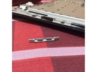
Remove the small black plastic spacer at the bottom of the left I/O frame.
-
-
-
Lift the left I/O frame up and out of the computer. Pay attention to the thin metal EMI fingers, as they may catch as you remove the left I/O frame.
-
To reassemble your device, follow these instructions in reverse order.
To reassemble your device, follow these instructions in reverse order.
Rückgängig: Ich habe diese Anleitung nicht absolviert.
15 weitere Personen haben diese Anleitung absolviert.


