Diese Version enthält möglicherweise inkorrekte Änderungen. Wechsle zur letzten geprüften Version.
Was du brauchst
-
-
Nimm eine Münze oder einen Spudger (Spatel), um die Akku-Verriegelungsschraube um 90 Grad im Uhrzeigersinn zu drehen.
-
-
-
Entferne die drei im gleichen Abstand an der Rückwand des Akkufachs verteilten Kreuzschlitzschrauben.
-
-
-
Fasse die L-förmige Speicherabdeckung am rechten Ende an und ziehe sie zu dir hin, so dass die Öffnung des Akkufachs frei liegt.
-
Hebe sie dann nach oben aus dem Computer heraus.
-
-
-
Entferne die folgenden drei Schrauben:
-
Eine 11 mm Kreuzschlitzschraube #00 in der Mitte des unteren Gehäuses. (Kopf: 5 mm Diameter, Dicke: 0,75 mm)
-
Zwei 14,5 mm Kreuzschlitzschrauben #00 (Kopf: 5 mm Diameter, Dicke: 0,75 mm)
-
-
-
Entferne die folgenden drei Schrauben von der Rückwand des Akku-Gehäuses:
-
Eine 3 mm Kreuzschlitzschraube #0. (Kopf: 2,75 mm Diameter)
-
Zwei 4 mm Kreuzschlitzschrauben #0 auf jeder Seite. (Kopf: 2,75 mm Diameter)
-
-
-
Entferne die beiden Kreuzschlitzschrauben auf beiden Seiten der rechten Wand des Akkufachs (nicht die, die sich direkt neben dem Akkuanschluss befinden).
-
Zwei 6,25 mm Kreuzschlitzschrauben #000. (Kopf: 4 mm Diameter, Dicke: 0,5 mm)
-
-
-
Entferne die vier gekennzeichneten Kreuzschlitzschrauben an der Vorderwand des Akkufachs. Wenn du von links aus arbeitest, entferne die 2., 4., 7. und 9. Schraube.
-
Vier 3,25 mm Kreuzschlitzschrauben #000. (Kopf: 4 mm Diameter, Dicke: 0,4 mm)
-
-
-
Entferne die folgenden vier Schrauben auf der Rückseite des Computers:
-
Zwei 11 mm Kreuzschlitzschrauben #00, mit Schaft (2,2 mm Diameter x 2 mm Länge) (Kopf: 3,2 mm Diameter , Dicke: 0,5 mm)
-
Zwei 7,25 mm Kreuzschlitzschrauben #00, mit Schaft (2 mm Diameter, 3,75 mm Länge) (Kopf: 3,2 mm Diameter, Dicke 0,5mm)
-
-
-
Entferne die beiden Kreuzschlitzschrauben von der rechten Seite des Computers. Das ist die Seite mit dem optischen Laufwerk.
-
Zwei 5,2 mm Kreuzschlitzschrauben #00 mit Schaft (Diameter: 2,3 mm,Länge: 3,25 mm) (Kopf: 3,2 mm Diameter, 0,5 mm Dicke)
-
-
-
Verwende ein Öffnungswerkzeug aus Plastik, eine abgelaufene Kreditkarte oder eine ähnlich dicke Karte, um das obere Gehäuse aufzuhebeln, indem du in der linken oberen Ecke beginnst und dich zur Vorderseite des Computers vorarbeitest.
-
-
-
Halte das obere Gehäuse hoch und ziehe die schwarze Lasche am Steckerende des silbernen Flachbandkabels von seinem Anschluss auf dem Logic Board weg.
-
-
-
Dieser Schritt ist noch nicht übersetzt. Hilf mit, ihn zu übersetzen!
-
Disconnect the MagSafe board cable from the logic board by pulling the snap-in connector out (to the right).
-
-
Dieser Schritt ist noch nicht übersetzt. Hilf mit, ihn zu übersetzen!
-
Remove the single 9 mm Phillips screw securing the left speaker to the lower case.
-
Lift the left speaker out of its housing and set it to the side.
-
-
Dieser Schritt ist noch nicht übersetzt. Hilf mit, ihn zu übersetzen!
-
Remove the following 3 screws:
-
Two 7.5 mm Phillips from either end of the left I/O frame.
-
One 9 mm Phillips from the middle of the left I/O frame.
-
Remove the small black plastic spacer at the bottom of the left I/O frame.
-
-
Dieser Schritt ist noch nicht übersetzt. Hilf mit, ihn zu übersetzen!
-
Lift the left I/O frame up and out of the computer. Pay attention to the thin metal EMI fingers, as they may catch as you remove the left I/O frame.
-
-
Dieser Schritt ist noch nicht übersetzt. Hilf mit, ihn zu übersetzen!
-
Peel up the foil tape between the fan and the optical drive.
-
-
Dieser Schritt ist noch nicht übersetzt. Hilf mit, ihn zu übersetzen!
-
Use a spudger to move the gray display data and black speaker cables to the right. This will reveal a silver screw securing the fan housing to the lower case.
-
-
Dieser Schritt ist noch nicht übersetzt. Hilf mit, ihn zu übersetzen!
-
Disconnect the orange optical drive ribbon cable from the logic board.
-
-
Dieser Schritt ist noch nicht übersetzt. Hilf mit, ihn zu übersetzen!
-
Peel up the small black rubber cover from the right side of the heat sink.
-
-
Dieser Schritt ist noch nicht übersetzt. Hilf mit, ihn zu übersetzen!
-
Disconnect the black fan connector and two temperature sensor connectors from the logic board by pulling/prying them directly up.
-
-
Dieser Schritt ist noch nicht übersetzt. Hilf mit, ihn zu übersetzen!
-
Remove the following 6 screws:
-
One 3 mm Phillips on the right side of the fan.
-
One 6 mm Phillips on the left side of the fan.
-
Four 9 mm Phillips securing the heat sink to the lower case.
-
-
Dieser Schritt ist noch nicht übersetzt. Hilf mit, ihn zu übersetzen!
-
Hold the heat sink with one hand and the fan with your other hand, and lift the heat sink and fan assembly out of the computer. The fan is attached to the heat sink only with a strip of black felt tape, so be sure to remove both parts as a unit.
-
-
Dieser Schritt ist noch nicht übersetzt. Hilf mit, ihn zu übersetzen!
-
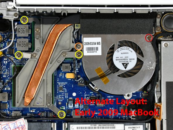
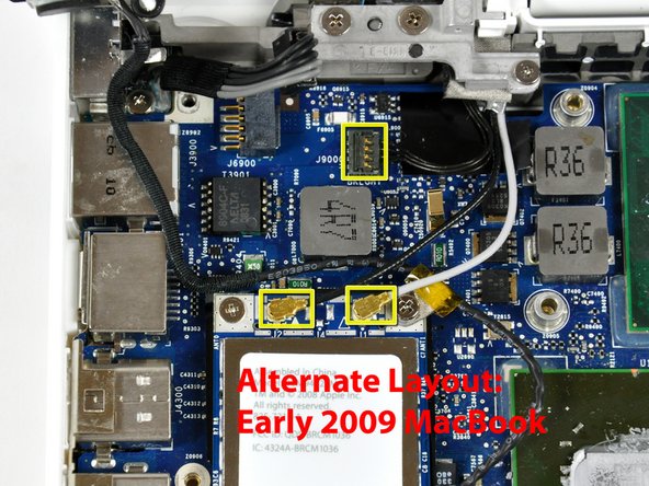
Disconnect the three antenna cables from the Airport card, and the black inverter cable from the logic board.
-
-
Dieser Schritt ist noch nicht übersetzt. Hilf mit, ihn zu übersetzen!
-
Remove the following 2 screws from the Airport card:
-
One 3 mm Phillips from the left side.
-
One 8 mm (with a large 2 mm head) Phillips from the right side.
-
-
Dieser Schritt ist noch nicht übersetzt. Hilf mit, ihn zu übersetzen!
-
Grasp the Airport card at its top and slide it toward the screen and out of the computer.
-
-
Dieser Schritt ist noch nicht übersetzt. Hilf mit, ihn zu übersetzen!
-
Use a spudger to disconnect the left speaker connector from the logic board.
-
Lift the left speaker out of the computer.
-
-
Dieser Schritt ist noch nicht übersetzt. Hilf mit, ihn zu übersetzen!
-
Disconnect the display data cable by pulling up on the black plastic pull-tab. If there is no pull-tab on the top of the connector, it may be helpful to use a spudger to disconnect this connector.
-
-
Dieser Schritt ist noch nicht übersetzt. Hilf mit, ihn zu übersetzen!
-
Disconnect the newly-revealed hard drive cable from the logic board.
-
-
Dieser Schritt ist noch nicht übersetzt. Hilf mit, ihn zu übersetzen!
-
Use a spudger to disconnect the speaker connector and bluetooth connector from the logic board.
-
-
Dieser Schritt ist noch nicht übersetzt. Hilf mit, ihn zu übersetzen!
-
Use a spudger to carefully disconnect the microphone cable from the logic board. You'll want to work from side to side, and slowly wiggle the connector out of its socket.
-
-
Dieser Schritt ist noch nicht übersetzt. Hilf mit, ihn zu übersetzen!
-
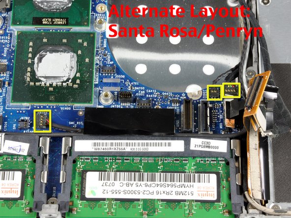
Deroute the microphone cable from the silver metal clip just above the right RAM slot.
-
-
Dieser Schritt ist noch nicht übersetzt. Hilf mit, ihn zu übersetzen!
-
Use a spudger to carefully pry the battery connector up and disconnect it from the logic board.
-
-
Dieser Schritt ist noch nicht übersetzt. Hilf mit, ihn zu übersetzen!
-
Remove the three 3 mm Phillips screws securing the logic board to the lower case.
-
-
Dieser Schritt ist noch nicht übersetzt. Hilf mit, ihn zu übersetzen!
-
Lift the logic board up from the right side, and slide it up and out of the computer.
-


Rückgängig: Ich habe diese Anleitung nicht absolviert.
5 weitere Nutzer:innen haben diese Anleitung absolviert.
