Diese Version enthält möglicherweise inkorrekte Änderungen. Wechsle zur letzten geprüften Version.
Was du brauchst
-
-
Entferne die folgenden zehn Schrauben, mit denen das untere Gehäuse am oberen Gehäuse befestigt ist:
-
Zwei 2,3 mm P5 Pentalobe Schrauben
-
Acht 3,0 mm P5 Pentalobe Schrauben
-
-
-
Versuche mit den Fingern zwischen das obere und das untere Gehäuse zu kommen.
-
Ziehe das untere Gehäuse behutsam vom Oberen weg.
-
Entferne das untere Gehäuse und lege es zur Seite.
-
-
-
Das untere Gehäuse ist in der Mitte durch zwei Plastikklammern mit dem oberen Gehäuse verbunden.
-
-
-
Entferne die Plastikabdeckung über der Platine des Akkuanschlusses.
-
-
-
Entferne die folgenden Schrauben, mit denen die Platine des Akkuanschlusses am Logic Board befestigt ist:
-
Zwei 2,8 mm T6 Torx Schrauben
-
Eine 7,0 mm T6 Torx Paß-Schulterschraube
-
-
-
Mit einer Pinzette kannst du die Plastikabdeckung rechts an der Platine des Akkuanschlusses entfernen.
-
-
-
Entferne die 6,4 mm T6 Torx Breitkopfschraube, mit der die Platine des Akkuanschlusses am Logic Board befestigt ist.
-
-
-
Ziehe die Platine des Akkuanschlusses vorsichtig vom Logic Board ab.
-
Es empfiehlt sich, die Batteriekabel nur leicht zu biegen, um die Platine über dem Logic Board und aus dem Weg zu halten.
-
-
-
Schnapp dir den Interposer mit einer Pinzette.
-
Hebe den Interposer aus dem Logic Board heraus und entferne ihn.
-
-
-
Mit dem flachen Ende eines Spudgers kannst du die rechte Seite des Anschlusses vom EA Board Datenkabel lösen.
-
-
-
Führe das flache Ende des Spudgers unter die linke Seite des EA Board Datenkabelanschlusses.
-
Drehe den Spudger vorsichtig hin und her, um den Anschluss des EA Board Datenkabels aus dem Stecker auf dem Logic Board zu lösen.
-
-
-
-
Heble den SSD Kabelstecker mit dem flachen Ende eines Spatels von der Buchse auf dem Logic Board.
-
Schiebe den SSD Kabelstecker aus dem Weg.
-
-
-
Fahre mit der Spudgerspitze unter den Kabelstecker des rechten Lautsprechers.
-
Ziehe den Kabelstecker des rechten Lautsprechers vorsichtig aus seiner Buchse auf dem Logic Board.
-
-
-
Entferne die folgenden Torx T5 Schrauben, die den rechten Lautsprecher am oberen Gehäuse befestigen:
-
Eine schwarze 6,8 mm Schraube
-
Eine silberfarbene 6,3 mm Schraube
-
Eine schwarze 4,9 mm Schraube
-
-
-
Heble das Kopfhöreranschlusskabel mit dem flachen Ende eines Spudgers aus seiner Buchse auf dem Logic Board.
-
-
-
Führe die Spitze eines Spudgers unter den Kabelstecker des linken Lautsprechers.
-
Heble den Kabelstecker des linken Lautsprechers vorsichtig aus seiner Buchse auf dem Logic Board.
-
-
-
Entferne die folgenden Torx T5 Schrauben, die den linken Lautsprecher am oberen Gehäuse befestigen:
-
Eine schwarze 6,8 mm Schraube
-
Eine silberfarbene 6,3 mm Schraube
-
Eine schwarze 4,9 mm Schraube
-
-
-
Drücke die Plastikfederleiste des SSD-Fachs mit dem Daumen (oder einem anderen Finger) ein, so dass die beiden Clips an der Vorderseite des Geräts frei werden.
-
Halte die Federleiste gedrückt und kippe die SSD Einheit aus ihrer Ausbuchtung.
-
-
Dieser Schritt ist noch nicht übersetzt. Hilf mit, ihn zu übersetzen!
-
Remove three 2.2 mm T5 Torx screws from each side of the battery (six screws total).
-
-
Dieser Schritt ist noch nicht übersetzt. Hilf mit, ihn zu übersetzen!
-
To protect your display, place a sheet of aluminum foil between the display and keyboard and leave it there while you work.
-
-
Dieser Schritt ist noch nicht übersetzt. Hilf mit, ihn zu übersetzen!
-
Now that your MacBook Pro is fully prepped, it's time to prep yourself.
-
Wear eye protection when handling and applying the adhesive remover. (Eye protection is included in your kit.)
-
Do not wear contact lenses without eye protection.
-
Protective gloves are also included in your kit. If you are concerned about skin irritation, put your gloves on now.
-
-
Dieser Schritt ist noch nicht übersetzt. Hilf mit, ihn zu übersetzen!
-
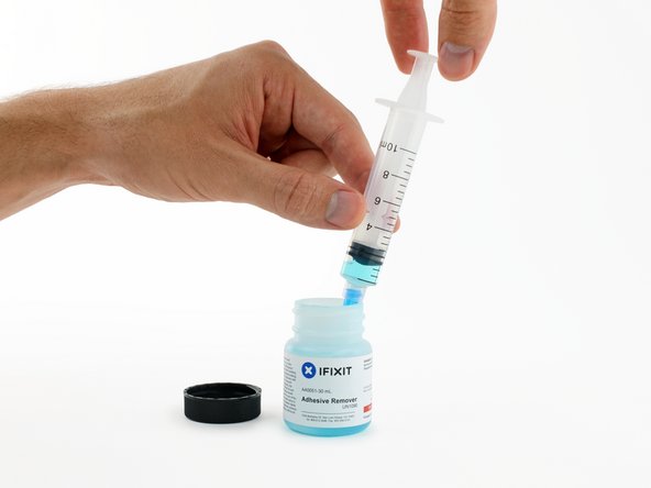
Open your container of adhesive remover.
-
Fill the syringe included in your kit with a small amount (approximately 1-2 milliliters) of adhesive remover.
-
Refill your syringe as needed throughout the rest of this procedure.
-
-
Dieser Schritt ist noch nicht übersetzt. Hilf mit, ihn zu übersetzen!
-
Apply a small amount of adhesive remover (approximately 1 ml) evenly under the edge of the leftmost battery cell.
-
Wait 2-3 minutes for the liquid adhesive remover to penetrate underneath the battery cell before you proceed to the next step.
-
-
Dieser Schritt ist noch nicht übersetzt. Hilf mit, ihn zu übersetzen!
-
Insert the flat edge of a spudger or plastic card underneath the leftmost battery cell.
-
Run your tool along the bottom perimeter of the battery cell and lift to begin separating the adhesive.
-
-
Dieser Schritt ist noch nicht übersetzt. Hilf mit, ihn zu übersetzen!
-
Insert the spudger along the left-hand side of the leftmost battery cell.
-
Run the spudger up along the left side of the leftmost battery cell.
-
Slightly pry the leftmost battery cell to release it from the adhesive.
-
-
Dieser Schritt ist noch nicht übersetzt. Hilf mit, ihn zu übersetzen!
-
Repeat the above steps to separate the adjacent battery cell from its adhesive:
-
Apply a small amount (about 1 ml) of liquid adhesive remover under the battery cell.
-
Wait 2-3 minutes for the adhesive remover to penetrate and soften the adhesive.
-
Carefully wedge a spudger or plastic card inwards, being careful to not damage the battery, and separate the battery cell from the adhesive securing it to your MacBook Pro.
-
-
Dieser Schritt ist noch nicht übersetzt. Hilf mit, ihn zu übersetzen!
-
Insert the flat end of a spudger underneath the larger leftmost battery cell.
-
Carefully wedge the spudger inwards, being careful to not damage the battery cells.
-
Pry the larger leftmost battery cell up off the upper case.
-
-
Dieser Schritt ist noch nicht übersetzt. Hilf mit, ihn zu übersetzen!
-
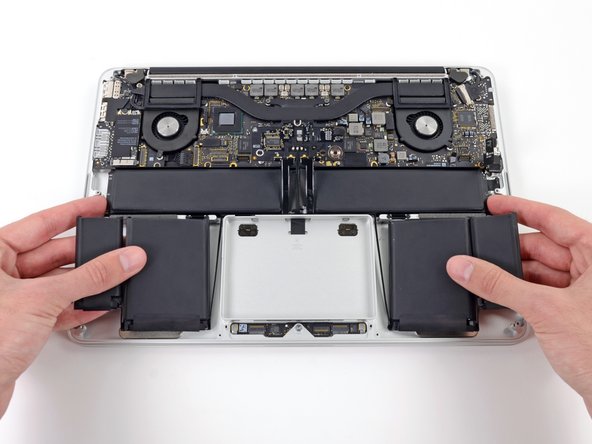
Grasp the battery cells and gently move (but do not remove) them from their recess in the upper case.
-
Leave the battery cells resting on top of the upper case as shown in the third picture.
-
-
Dieser Schritt ist noch nicht übersetzt. Hilf mit, ihn zu übersetzen!
-
Switch sides and repeat the above procedure for the two battery cells on the right-hand side of the MacBook Pro.
-
Remember to add about 1 ml of liquid adhesive remover under each battery cell, and wait 2-3 minutes for it to penetrate before prying up the cell.
-
-
Dieser Schritt ist noch nicht übersetzt. Hilf mit, ihn zu übersetzen!
-
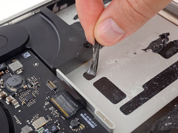
Lift the battery as a whole up out of the upper case, and remove the battery.
-
With a little luck, you can slowly pull out each strip of adhesive with your fingers.
-
Otherwise, soak each section of adhesive with a bit of adhesive remover for 2-3 minutes, and then scrape it out with an opening pick or one of the other tools in your kit. This can take quite a bit of work, so be patient.
-
Mop up any remaining adhesive remover and give your MacBook Pro a few minutes to air dry.
-
Calibrate your new battery before using it: allow it to drain overnight, then charge it to 100% and drain it again until your MacBook Pro shuts down automatically. Charge it again and use it normally.
-


Rückgängig: Ich habe diese Anleitung nicht absolviert.
2 weitere Nutzer:innen haben diese Anleitung absolviert.

Ein Kommentar
Step 14 and Step 18 (disconnecting the speakers) are not really useful. But there should be a reason I didn’t catch for these steps. Thank you by the way, it was really clear and it worked perfectly!