Einleitung
Use this guide to replace the upper case assembly that includes the keyboard and battery indicator.
Was du brauchst
-
-
Remove the following ten screws:
-
Three 14.4 mm Phillips #00 screws
-
Three 3.5 mm Phillips #00 screws
-
Four 3.5 mm shouldered Phillips #00 screws
-
-
-
Use your fingers to pry the lower case away from the body of the MacBook near the vent.
-
Remove the lower case.
-
-
-
Use the edge of a spudger to pry the battery connector upwards from its socket on the logic board.
-
-
-
Bend the battery cable slightly away from its socket on the logic board so it does not accidentally connect itself while you work.
-
-
-
Use the edge of a spudger to gently pry the fan connector up and out of its socket on the logic board.
-
-
-
Remove the following three screws securing the fan to the logic board:
-
One 7.2 mm T6 Torx screw
-
Two 5.3 mm T6 Torx screws
-
-
-
Lift the fan out of its recess in the logic board, minding its cable that may get caught.
-
-
-
Use the tip of a spudger to pull the right speaker/subwoofer cable out from under the retaining finger molded into the upper case.
-
Pull the right speaker/subwoofer cable upward to lift the connector out of its socket on the logic board.
-
-
-
Disconnect the following four cables:
-
AirPort/Bluetooth cable
-
Optical drive cable
-
Hard drive cable
-
Trackpad cable
-
-
-
Use your fingernail to flip up the retaining flap on the keyboard ribbon cable ZIF socket.
-
Use the tip of a spudger to pull the keyboard ribbon cable out of its socket.
-
-
-
If present, remove the small strip of black tape covering the keyboard backlight cable socket.
-
-
-
Use the tip of a spudger or your fingernail to flip up the retaining flap on the keyboard backlight ribbon cable ZIF socket.
-
Pull the keyboard backlight ribbon cable out of its socket.
-
-
-
Use the flat end of a spudger to pry the sleep sensor/battery indicator connector up from its socket on the logic board.
-
-
-
-
Grab the plastic pull tab secured to the display data cable lock and rotate it toward the DC-In side of the computer.
-
Pull the display data cable straight out of its socket on the logic board.
-
-
-
Remove the following nine screws:
-
Five 3.6 mm T6 Torx screws
-
Two 4.3 mm T6 Torx screws
-
Two 7.2 mm T6 Torx screws
-
Five 3.0 mm T6 screws
-
Two 3.6 mm T6 screws
-
Two 6.7 mm T6 screws
-
-
-
Remove the following two screws:
-
One 8.6 mm Phillips screw
-
One 5.5 mm Phillips screw
-
Remove the display data cable retainer from the upper case.
-
-
-
Use the tip of a spudger to gently peel the microphone off the adhesive securing it to the upper case.
-
-
-
Minding the many connectors near its edges, lift the logic board from the end nearest the optical drive.
-
Without flexing the board, maneuver it out of the upper case, minding the flexible connection to the DC-In board that may get caught in the upper case.
-
Remove the logic board.
-
-
-
Remove the following two screws:
-
One 5.6 mm Tri-point screw
-
One 13 mm Tri-point screw
-
-
-
Carefully peel the battery warning label off the upper case between the battery and the optical drive.
-
-
-
Use the attached plastic pull tab to help remove the battery from the upper case.
-
-
-
Remove the two Phillips screws securing the hard drive bracket to the upper case.
-
Remove the hard drive bracket.
-
-
-
Use the attached pull tab to lift the hard drive out of the upper case.
-
Pull the hard drive cable away from the body of the hard drive.
-
Remove the hard drive.
-
-
-
Remove the following four screws:
-
Two 3 mm Phillips screws
-
Two 9.7 mm Phillips screws
-
-
-
Carefully peel up the thin IR sensor/sleep LED ribbon cable from the adhesive securing it to the upper case.
-
-
-
Pull the front hard drive bracket containing the IR sensor/sleep LED away from the front edge of the upper case.
-
Remove the hard drive cable.
-
-
-
Carefully move the AirPort/Bluetooth ribbon cable out of the way as you peel the camera cable off the adhesive securing it to the subwoofer and the AirPort/Bluetooth bracket.
-
De-route the camera cable out from under the retaining finger molded into the AirPort/Bluetooth bracket.
-
-
-
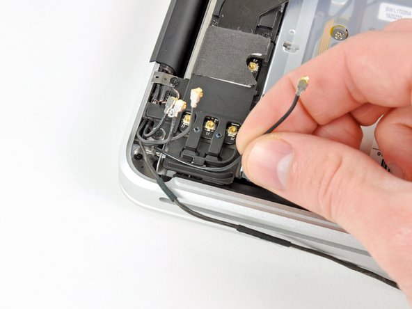
Disconnect the four antenna connectors boxed in red in the first picture.
-
To do so, use the tip of a spudger to pry their connectors up from the sockets on the AirPort/Bluetooth board.
-
De-route each of the cables from their channels in the AirPort/Bluetooth bracket.
-
-
-
Remove the following five screws:
-
Two 10.3 mm Phillips screws
-
Two 3.1 mm Phillips screws
-
One 5 mm Phillips screw
-
-
-
Pull the AirPort/Bluetooth assembly and the Subwoofer upward near the center of the side of the optical drive until they clear each other.
-
Remove the AirPort/Bluetooth board assembly.
-
-
-
Remove the three 2.7 mm Phillips screws securing the optical drive to the upper case.
-
-
-
Lift the optical drive from the edge nearest the display and remove it from the upper case.
-
-
-
Use a plastic opening tool or another thin prying object to carefully pry the right speaker up from the adhesive securing it to the upper case.
-
Pry up along the edge of the right speaker until it is separated from the upper case.
-
-
-
Remove two of the three 6 mm T8 Torx screws securing the right side of the display to the upper case.
-
-
-
Remove two of the three 6 mm T8 Torx screws securing the left side of the display to the upper case.
-
-
-
Open your MacBook Pro so the display is perpendicular to the upper case.
-
Place your opened MacBook Pro on a table as pictured.
-
While holding the display and upper case together with your left hand, remove the remaining T8 Torx screw from the lower display bracket.
-
-
-
Remove the last remaining T8 Torx screw securing the display to the upper case.
-
-
-
Grab the upper case with your right hand and rotate it slightly toward the top of the display so the upper display bracket clears the edge of the upper case.
-
Rotate the display slightly away from the upper case.
-
Lift the display up and away from the upper case, minding any brackets or cables that may get caught.
-
Upper case remains.
-


To reassemble your device, follow these instructions in reverse order.
To reassemble your device, follow these instructions in reverse order.
Rückgängig: Ich habe diese Anleitung nicht absolviert.
Ein:e weitere:r Nutzer:in hat diese Anleitung absolviert.
