Diese Übersetzung enthält möglicherweise noch nicht die neuesten Änderungen der Original-Anleitung. Hilf mit, die Übersetzung zu aktualisieren oder sieh dir die Original-Anleitung an.
Was du brauchst
-
-
Eventuell befindet sich eine weiche Abdeckung über dem Verbinder, die du dann entfernen musst. Ziehe dann vorsichtig den Verbinder aus seinem Sockel auf dem Logic Board.
-
-
-
Ziehe den Verbinder des Kamerakabels in Richtung des optischen Laufwerks, um es vom Logic Board zu lösen.
-
-
-
Ziehe den Verbinder des optischen Laufwerks mit dem flachen Ende eines Spudgers senkrecht aus seinem Sockel.
-
-
-
-
Ziehe den Verbinder der Festplatte mit dem flachen Ende eines Spudgers senkrecht aus seinem Sockel.
-
-
-
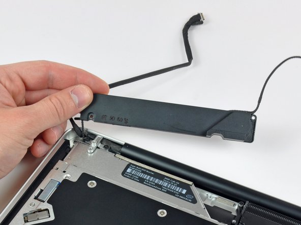
Der Subwoofer ist mit Kreuzschlitzschrauben am oberen Gehäuse befestigt. Drehe folgende Schrauben heraus:
-
Eine 3,8 mm
-
Eine 5 mm
-
-
-
Hebe den Subwoofer vom optischen Laufwerk weg, und lege ihn neben den Computer.
-
-
-
Entferne die beiden 10 mm Kreuzschlitzschrauben, die die Halterung für das Kamerakabel am oberen Gehäuse festhalten.
-
Hebe die Halterung für das Kamerakabel aus dem Gehäuse.
-
-
-
Entferne die drei 2,5 mm Kreuzschlitzschrauben, die das optische Laufwerk am Gehäuse befestigen.
-
Hebe das optische Laufwerk an der rechten Kante hoch und ziehe es aus dem Computer.
Install 2 outside screws first and then single inside screw to allow wiggle room to get outside screws in. Do not tighten screws until all are started.
-


Um dein Gerät wieder zusammenzusetzen, folge den Schritten in umgekehrter Reihenfolge.
Um dein Gerät wieder zusammenzusetzen, folge den Schritten in umgekehrter Reihenfolge.
Rückgängig: Ich habe diese Anleitung nicht absolviert.
Ein:e weitere:r Nutzer:in hat diese Anleitung absolviert.
Besonderer Dank geht an diese Übersetzer:innen:
81%


Diese Übersetzer:innen helfen uns, die Welt zu reparieren! Wie kann ich mithelfen?
Hier starten ›

Ein Kommentar
Bonsoir. Le tuto est très clair, mais je voudrais savoir s’il est applicable sur la version 15” du MBP 10. Amicalement, Marc.
It is not necessary to remove the camera cable connector (step 5) or the camera cable connector (step 10). Simply push the camera cable gently aside to remove one of the three screws securing the optical drive (step 11). Gently wiggle the optical drive from under the camera cable connector and go to step 12. Less chance of ruining your motherboard!
tomhart - Antwort
Absolutely. Leave it alone, you don’t need to run the risks of removing this cable, I did the replacement fine without it
Steven Taylor -
It does indeed come out of the connector, but the picture makes it hard to see how; the connector it goes into sits on top of the board—however, I, too, ripped mine off the board trying to remove it; I only got it out of the clip after I tore it off. SIMPLY DONT; it's unnecessary. I plan to solder it back if one of my Robotics club friends lets me borrow a soldering iron.
Rachel - Antwort
Alors je déconseille très fortement de toucher ce connecteur, il est extrêmement fragile. De plus, cela n’a pas d’incidence sur la suite des opérations
Laskoni - Antwort
The author needs to go back through this guide and correct lots of order mistakes. The fan was removed in steps 3-5 yet it’s still being shown installed in steps 19-22.
plink53 - Antwort
The 4-pin push connector for the sub-woofer is near impossible to reconnect
It mates with a female connector that sits on top of 4 tiny solder points (it's held on by a spot of glue, I believe), and when applying ANY pressure to connect, the side clip(s) will snap off. Then the connector itself will become unglued. It would be simple enough to connect the 2 parts, then place a drop of glue on the logic board after positioning it above the solder points, but the female connector broke apart in my hand. So now screwed, with no way to connect sub/ R speaker without installing another logic board. Fan connector looks to be exactly the same
Peter Watkins - Antwort