Diese Version enthält möglicherweise inkorrekte Änderungen. Wechsle zur letzten geprüften Version.
Was du brauchst
-
-
Ziehe die beiden Laschen, die den Akku im Laptop halten, mit den Fingern vom Akku weg und nimm den Akku aus dem Rechner heraus.
-
-
-
Entferne die drei Kreuzschlitz Schrauben von der Abdeckung des Arbeitsspeichers.
-
-
-
Hebe die Abdeckung hoch genug, um sie greifen zu können und ziehe sie vom Rechner weg.
-
-
-
Entferne die beiden 2,8 mm Kreuzschlitz Schrauben im Bereich des Akkufachs.
-
-
-
Entferne die folgenden sechs Schrauben:
-
Jeweils eine 10 mm T6 Torx Schraube rechts und links vom Arbeitsspeicher.
-
Vier 14,5 mm Kreuzschlitz Schrauben entlang des Bildschirm-Scharniers.
-
-
-
Entferne die vier 3,2 mm Kreuzschlitz Schrauben entlang der Seite mit den Anschlüssen des Computers.
-
-
-
Drehe den Computer um 90° und entferne die beiden 3,2 mm Kreuzschlitz Schrauben von der Rückseite des Computers.
-
-
-
Drehe den Computer noch einmal um 90° und entferne die vier 3,2 mm Kreuzschlitz Schrauben von der Seite des Computers.
-
-
-
Hebe die Rückseite des oberen Gehäuses an und arbeite dich mit deinen Fingern an beiden Seiten des Computers nach unten und löse die Klammern, die das obere Gehäuse mit dem Rest des Computers verbinden.
-
Wenn das obere Gehäuse sich noch nicht löst, bewege es auf und ab, um noch weitere Klammern zu lösen. Es gibt einige versteckte Klammern, die sich lösen müssen.
-
-
-
Trenne das Trackpad- und Tastatur-Flachbandkabel von der Hauptplatine. Möglicherweise ist der Anschluss mit einem Klebestreifen abgedeckt.
-
Entferne das obere Gehäuse.
-
-
Dieser Schritt ist noch nicht übersetzt. Hilf mit, ihn zu übersetzen!
-
Disconnect the three antenna cables attached to the Airport Extreme card.
-
-
Dieser Schritt ist noch nicht übersetzt. Hilf mit, ihn zu übersetzen!
-
Deroute the Airport antenna cables from their channel in the left speaker.
-
-
Dieser Schritt ist noch nicht übersetzt. Hilf mit, ihn zu übersetzen!
-
Disconnect the iSight cable from the logic board by sliding the cable to the left and out of its connector.
-
-
Dieser Schritt ist noch nicht übersetzt. Hilf mit, ihn zu übersetzen!
-
Disconnect the inverter cable from the logic board by placing a spudger beneath the cable and lifting up.
-
-
-
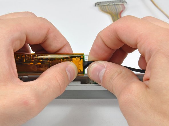
Dieser Schritt ist noch nicht übersetzt. Hilf mit, ihn zu übersetzen!
-
Disconnect the display data cable from the logic board by pulling sideways.
-
-
Dieser Schritt ist noch nicht übersetzt. Hilf mit, ihn zu übersetzen!
-
Remove the silver T6 Torx securing the ground loop in the display data cable to the casing.
-
-
Dieser Schritt ist noch nicht übersetzt. Hilf mit, ihn zu übersetzen!
-
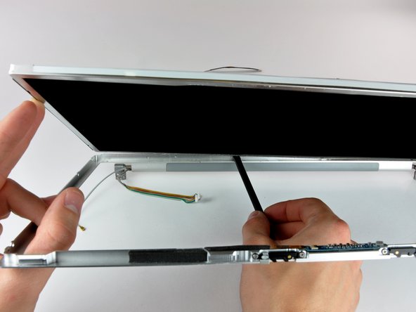
Support the display with one hand while removing the following 3 screws:
-
Two 9.5 mm silver T6 Torx screws with threads on only part of the shaft on the inside of the display hinges.
-
One 9.5 mm silver T6 Torx screw with threads on the entire shaft on the outside of the left hinge.
-
-
Dieser Schritt ist noch nicht übersetzt. Hilf mit, ihn zu übersetzen!
-
Grasp the display assembly on both sides and lift it up and out of the computer.
-
-
Dieser Schritt ist noch nicht übersetzt. Hilf mit, ihn zu übersetzen!
-
Remove the two 5 mm Phillips screws from the lower left and right corners of the display (two screws total).
-
-
Dieser Schritt ist noch nicht übersetzt. Hilf mit, ihn zu übersetzen!
-
Insert the flat end of a spudger perpendicular to the face of the display between the plastic strip attached to the rear bezel and the front bezel.
-
With the spudger still inserted, rotate it away from the display to separate the front and rear bezels.
-
Work along the left edge of the display until the rear bezel is evenly separated from the front bezel.
-
-
Dieser Schritt ist noch nicht übersetzt. Hilf mit, ihn zu übersetzen!
-
Insert the flat end of a spudger perpendicular to the face of the display between the plastic strip attached to the rear bezel and the front bezel.
-
With the spudger still inserted, rotate it away from the display to separate the front and rear bezels.
-
Work along the right edge of the display until the rear bezel is evenly separated from the front bezel.
-
-
Dieser Schritt ist noch nicht übersetzt. Hilf mit, ihn zu übersetzen!
-
Insert the flat end of a spudger between the front bezel and the plastic strip attached to the rear bezel near the screw holes at the bottom corners of the display.
-
Rotate your spudger toward the rear bezel to separate it from the front bezel.
-
If necessary, enlarge the gap between the lower edge of the rear bezel and the clutch cover until the two components are completely separated.
-
-
Dieser Schritt ist noch nicht übersetzt. Hilf mit, ihn zu übersetzen!
-
Lift the rear bezel by its bottom edge and rotate it away from the display assembly to separate the top edge.
-
Remove the rear display bezel from the display assembly.
-
-
Dieser Schritt ist noch nicht übersetzt. Hilf mit, ihn zu übersetzen!
-
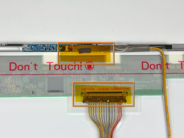
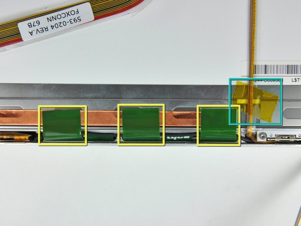
Remove the pieces of yellow kapton tape from the bottom left corner of the display.
-
Remove the pieces of tape securing the display data cable and camera cable to the display.
-
Peel the three green antenna ground straps off the copper tape along the bottom edge of the LCD.
-
Remove the piece of tape securing the camera cable to the LCD.
-
-
Dieser Schritt ist noch nicht übersetzt. Hilf mit, ihn zu übersetzen!
-
Carefully peel the camera cable off the foam tape along the top edge of the LCD.
-
-
Dieser Schritt ist noch nicht übersetzt. Hilf mit, ihn zu übersetzen!
-
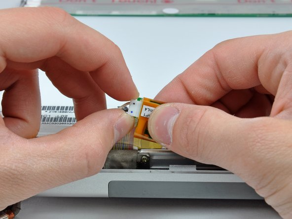
Use the tip of a spudger and carefully flip the ZIF connector bar up to release the before the camera cable.
-
Gently pull the camera cable away from its socket on the camera board.
-
-
Dieser Schritt ist noch nicht übersetzt. Hilf mit, ihn zu übersetzen!
-
Pull the display data cable connector away from its socket on the LCD.
-
-
Dieser Schritt ist noch nicht übersetzt. Hilf mit, ihn zu übersetzen!
-
Remove the four black Phillips screws along the left and right edges of the display (eight screws total).
-
-
Dieser Schritt ist noch nicht übersetzt. Hilf mit, ihn zu übersetzen!
-
Use the flat end of a spudger to gently lift one of the top corners of the LCD out of the front bezel.
-
-
Dieser Schritt ist noch nicht übersetzt. Hilf mit, ihn zu übersetzen!
-
Work your way along the top edge of the LCD, slowly prying the attached steel strip away from the front bezel.
-
-
Dieser Schritt ist noch nicht übersetzt. Hilf mit, ihn zu übersetzen!
-
Now that the top edge is free, slightly lift the LCD out of the front bezel for enough room to pry the steel strip along the lower edge of the LCD away from the front bezel.
-
Pry along the lower edge of the LCD until it is freed from the adhesive on the front bezel.
-
-
Dieser Schritt ist noch nicht übersetzt. Hilf mit, ihn zu übersetzen!
-
Lift the inverter out of the clutch cover.
-
Disconnect the LCD backlight connector from its socket on the inverter board.
-
-
Dieser Schritt ist noch nicht übersetzt. Hilf mit, ihn zu übersetzen!
-
Lift the LCD out of the front bezel, minding any cables that may get caught.
-
-
Dieser Schritt ist noch nicht übersetzt. Hilf mit, ihn zu übersetzen!
-
Lift the inverter out of the clutch cover.
-
Disconnect the inverter cable from the inverter by pulling its cable away from the socket on the inverter board.
-
Remove the inverter and set it aside.
-
-
Dieser Schritt ist noch nicht übersetzt. Hilf mit, ihn zu übersetzen!
-
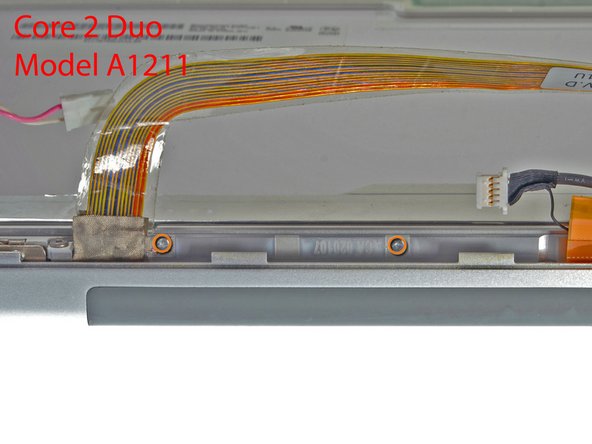
If you have a Core Duo machine, refer to picture 1 and remove three Phillips screws connecting the clutch assembly to the lower edge of the front display bezel near the display data cable.
-
If you have a Core 2 Duo Model A1211 machine, refer to picture 2 and remove two Phillips screws connecting the clutch assembly to the lower edge of the front display bezel near the display data cable.
-
-
Dieser Schritt ist noch nicht übersetzt. Hilf mit, ihn zu übersetzen!
-
Remove the single black Phillips screw from behind the display data cable.
-
Slide the small steel bracket away from the right clutch hinge and remove it from the clutch assembly.
-
-
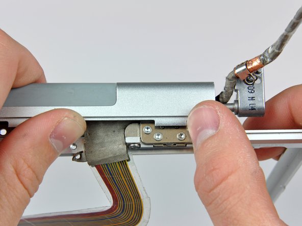
Dieser Schritt ist noch nicht übersetzt. Hilf mit, ihn zu übersetzen!
-
Remove the three Phillips screws along the inside of the clutch cover near the inverter/camera cable.
-
-
Dieser Schritt ist noch nicht übersetzt. Hilf mit, ihn zu übersetzen!
-
Push the open edge of the clutch cover away from the left clutch hinge to pop it off the clips attaching the two parts.
-
If necessary, repeat this process for the right side of the clutch assembly.
-
Remove the clutch assembly from the front display bezel.
-
-
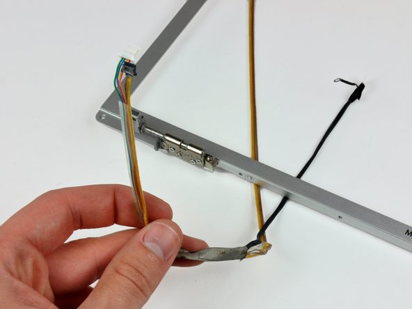
Dieser Schritt ist noch nicht übersetzt. Hilf mit, ihn zu übersetzen!
-
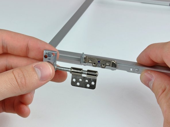
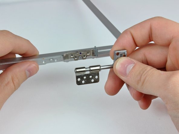
De-route the display data and inverter/camera cables around the clutch hinges and remove both cables.
-
-
Dieser Schritt ist noch nicht übersetzt. Hilf mit, ihn zu übersetzen!
-
Remove the four T6 Torx screws securing the left clutch hinge to the front display bezel.
-
Remove the left clutch hinge and set it aside.
-
-
Dieser Schritt ist noch nicht übersetzt. Hilf mit, ihn zu übersetzen!
-
Remove the four T6 Torx screws securing the right clutch hinge to the front display bezel.
-
Remove the right clutch hinge and set it aside.
-


Rückgängig: Ich habe diese Anleitung nicht absolviert.
7 weitere Nutzer:innen haben diese Anleitung absolviert.
