Diese Version enthält möglicherweise inkorrekte Änderungen. Wechsle zur letzten geprüften Version.
Was du brauchst
-
-
Benutze deine Finger und drücke bzw. ziehe die beiden Entriegelungslaschen vom Akku weg, und hebe den Akku aus dem Computer.
-
-
-
Entferne die drei identischen 2 mm Kreuzschlitzschrauben von der RAM Abdeckung.
-
Hebe die Abdeckung soweit hoch, dass du sie fassen kannst und ziehe sie weg vom Gehäuse zu dir hin.
-
-
-
Entferne die beiden 2,8 mm Kreuzschlitzschrauben im Akkufach in der Nähe der Verriegelung.
-
-
-
Entferne folgende sechs Schrauben:
-
Zwei 10 mm Torx T6 Schrauben auf jeder Seite des RAM- Einschubs.
-
Vier 14,5 mm Kreuzschlitzschrauben am Scharnier.
-
-
-
Entferne die vier 3,2 mm #00 Kreuzschlitzschrauben an der Seite mit den Anschlüssen.
-
-
-
Drehe den Computer um 90° und entferne die beiden 3,2 mm Kreuzschlitzschrauben auf der Rückseite des Computers.
-
-
-
-
Drehe den Computer weitere 90° und entferne die vier 3,2 mm Kreuzschlitzschrauben an der Seite des Computers.
-
-
-
Hebe das Gehäuse hinten hoch und arbeite dich dann mit den Fingern an den Seiten entlang nach vorne. Wenn die Seiten frei sind, dann bewege es auf und ab, sodass sich auch die Vorderkante ablöst.
-
Es gibt vier Kunststoffrasten über den DVD-Einschub und eine weitere links über dem Infrarotsensor. Diese Rasten lassen sich kaum lösen, ohne zu hebeln. Beim Zusammenbau sind sie auch wieder schwer einzurasten.
-
-
-
Trenne die Flachbandkabel des Trackpads und der Tastatur vom Logic Board ab, wobei du eventuell Klebebänder ablösen musst.
-
Entferne das Gehäuseoberteil.
-
-
Dieser Schritt ist noch nicht übersetzt. Hilf mit, ihn zu übersetzen!
-
Use a spudger to pry up the translucent plastic sheath covering the keyboard connector.
-
-
Dieser Schritt ist noch nicht übersetzt. Hilf mit, ihn zu übersetzen!
-
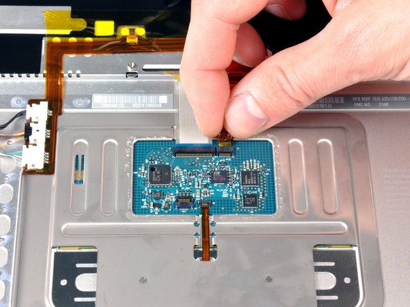
Use the tip of a spudger to flip up the black plastic flap locking down the keyboard ribbon cable.
-
-
Dieser Schritt ist noch nicht übersetzt. Hilf mit, ihn zu übersetzen!
-
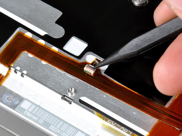
Peel up the orange tape covering the keyboard backlight connector.
-
-
Dieser Schritt ist noch nicht übersetzt. Hilf mit, ihn zu übersetzen!
-
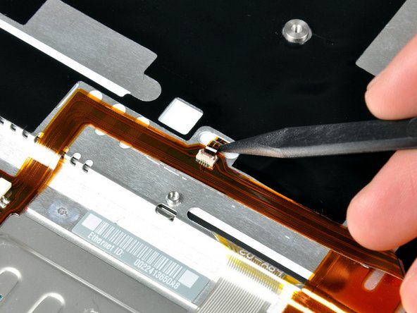
Use the tip of a spudger to flip up the brown plastic flap locking down the keyboard backlight ribbon cable.
-
Use a spudger or your finger to slide the keyboard backlight ribbon out of its connector.
-
-
Dieser Schritt ist noch nicht übersetzt. Hilf mit, ihn zu übersetzen!
-
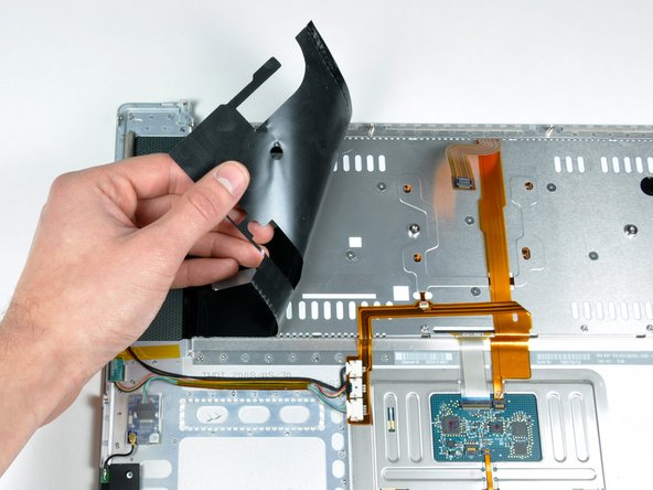
Peel back the black protective sheath on the right side of the upper case.
-
Similarly, peel the black protective sheath on the left side of the upper case.
-
-
Dieser Schritt ist noch nicht übersetzt. Hilf mit, ihn zu übersetzen!
-
Remove the 12 identical Phillips screws attaching the keyboard to the casing.
-
There are six locking tabs along the back edge of the keyboard holding it in place. These tabs must be straightened before you can remove the keyboard.
-
-
Dieser Schritt ist noch nicht übersetzt. Hilf mit, ihn zu übersetzen!
-
Slide the keyboard ribbon out of its connector.
-
-
Dieser Schritt ist noch nicht übersetzt. Hilf mit, ihn zu übersetzen!
-
Place the upper casing on its edge and use a spudger to push the keyboard away from the casing, poking the spudger through the central keyboard screw hole. Grasp the keyboard as it separates from the casing.
-
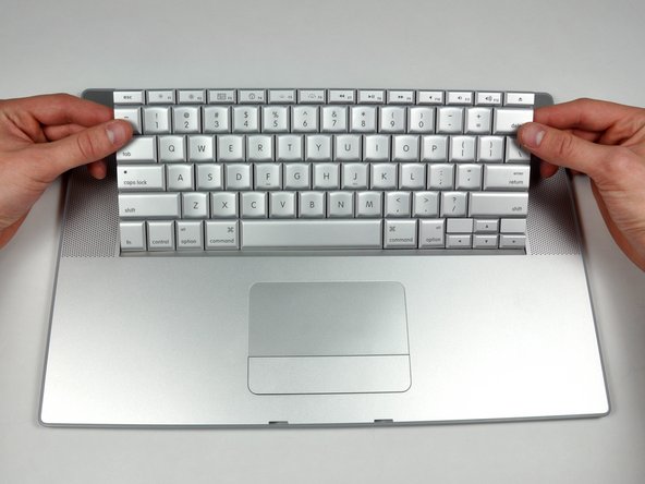
Maintaining your hold on the keyboard, lay the casing flat and gently bow the keyboard until the two tabs on either side of the keyboard come free.
-
Slide the keyboard away from the trackpad and out of the upper case.
-


Rückgängig: Ich habe diese Anleitung nicht absolviert.
152 weitere Nutzer:innen haben diese Anleitung absolviert.

2 Kommentare
Excellent guide as always. Both the keyboard I got from iFixIt and the guide worked perfectly. Thanks!
This was such an excellent fix-it guide. I was able to swap out my keyboard while watching the Seahawks lose to the St. Louis Rams (sadly). One recommendation: have 12 or so ziplock bags each numbered with a step number that requires a screw or part to be removed and put the screws/parts from that step in the bag and zip it closed. You won't mix up screw sizes from the various steps.
Thanks again to ifixit.com for this excellent repair tool. My new keyboard functions perfectly!!