Diese Version enthält möglicherweise inkorrekte Änderungen. Wechsle zur letzten geprüften Version.
Was du brauchst
-
-
Benutze deine Finger und drücke bzw. ziehe die beiden Entriegelungslaschen vom Akku weg, und hebe den Akku aus dem Computer.
-
-
-
Entferne die drei identischen 2 mm Kreuzschlitzschrauben von der RAM Abdeckung.
-
Hebe die Abdeckung soweit hoch, dass du sie fassen kannst und ziehe sie weg vom Gehäuse zu dir hin.
-
-
-
Entferne die beiden 2,8 mm Kreuzschlitzschrauben im Akkufach in der Nähe der Verriegelung.
-
-
-
Entferne folgende sechs Schrauben:
-
Zwei 10 mm Torx T6 Schrauben auf jeder Seite des RAM- Einschubs.
-
Vier 14,5 mm Kreuzschlitzschrauben am Scharnier.
-
-
-
Entferne die vier 3,2 mm #00 Kreuzschlitzschrauben an der Seite mit den Anschlüssen.
-
-
-
Drehe den Computer um 90° und entferne die beiden 3,2 mm Kreuzschlitzschrauben auf der Rückseite des Computers.
-
-
-
Drehe den Computer weitere 90° und entferne die vier 3,2 mm Kreuzschlitzschrauben an der Seite des Computers.
-
-
-
Hebe das Gehäuse hinten hoch und arbeite dich dann mit den Fingern an den Seiten entlang nach vorne. Wenn die Seiten frei sind, dann bewege es auf und ab, sodass sich auch die Vorderkante ablöst.
-
Es gibt vier Kunststoffrasten über den DVD-Einschub und eine weitere links über dem Infrarotsensor. Diese Rasten lassen sich kaum lösen, ohne zu hebeln. Beim Zusammenbau sind sie auch wieder schwer einzurasten.
-
-
-
Trenne die Flachbandkabel des Trackpads und der Tastatur vom Logic Board ab, wobei du eventuell Klebebänder ablösen musst.
-
Entferne das Gehäuseoberteil.
-
-
Dieser Schritt ist noch nicht übersetzt. Hilf mit, ihn zu übersetzen!
-
Disconnect the two or three antenna cables attached to the Airport Extreme card. Depending on your model, one of the three cables may be unused and capped with a black shrink tube.
-
-
Dieser Schritt ist noch nicht übersetzt. Hilf mit, ihn zu übersetzen!
-
Deroute the Airport antenna cables from their channel in the left speaker.
-
-
Dieser Schritt ist noch nicht übersetzt. Hilf mit, ihn zu übersetzen!
-
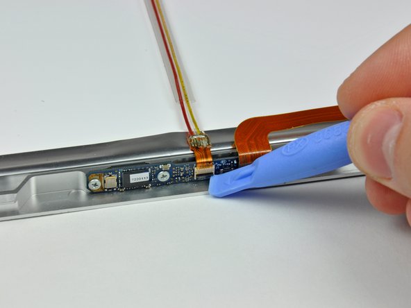
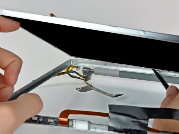
Disconnect the iSight cable from the logic board by sliding the cable to the left and out of its connector.
-
-
-
Dieser Schritt ist noch nicht übersetzt. Hilf mit, ihn zu übersetzen!
-
Support the display with one hand while removing the following screws:
-
One 9.5 mm silver T6 Torx screw with threads on only 3 mm of the shaft on the inside of the display hinges.
-
One 9.5 mm silver T6 Torx screw with threads on the entire shaft on the outside of the left hinge.
-
One 9.2 mm full thread T6 Torx screw securing the iSight cable ground loop to the fan.
-
-
Dieser Schritt ist noch nicht übersetzt. Hilf mit, ihn zu übersetzen!
-
Disconnect the inverter cable from the left I/O board by placing a spudger beneath the cable and lifting up.
-
-
Dieser Schritt ist noch nicht übersetzt. Hilf mit, ihn zu übersetzen!
-
Disconnect the display data cable from the logic board.
-
Remove the foam bumper from the top of the right hinge of the display.
-
-
Dieser Schritt ist noch nicht übersetzt. Hilf mit, ihn zu übersetzen!
-
Remove the silver 9.2 mm T6 Torx securing the ground loop in the display data cable to the casing.
-
-
Dieser Schritt ist noch nicht übersetzt. Hilf mit, ihn zu übersetzen!
-
Support the display with one hand while removing the following screw:
-
One 9.5 mm silver T6 Torx screw with threads on only 3 mm of the shaft on the inside of the display hinges.
-
-
Dieser Schritt ist noch nicht übersetzt. Hilf mit, ihn zu übersetzen!
-
Grasp the display assembly on both sides and lift it up and out of the computer.
-
-
Dieser Schritt ist noch nicht übersetzt. Hilf mit, ihn zu übersetzen!
-
Remove the 4.5 mm Phillips screws from the lower left and right corners of the display (two screws total). These screws have a .8 mm thick head.
-
-
Dieser Schritt ist noch nicht übersetzt. Hilf mit, ihn zu übersetzen!
-
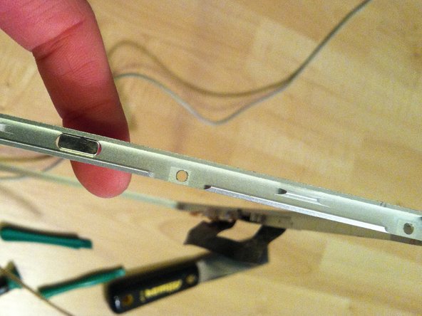
Insert the flat end of a spudger perpendicular to the face of the display between the plastic strip attached to the rear bezel and the front bezel.
-
With the spudger still inserted, rotate it away from the display to separate the front and rear bezels.
-
Work along the right edge of the display until the rear bezel is evenly separated from the front bezel.
-
-
Dieser Schritt ist noch nicht übersetzt. Hilf mit, ihn zu übersetzen!
-
Insert your spudger between the front and rear display bezels at the lower right corner of the display.
-
Pry the rear bezel away from the front bezel to slightly separate the bottom edge of the rear display bezel.
-
-
Dieser Schritt ist noch nicht übersetzt. Hilf mit, ihn zu übersetzen!
-
Insert the flat end of a spudger into the gap between the rear display bezel and the clutch cover.
-
Twist the spudger to separate the lower edge of the rear display bezel from the clutch cover.
-
Work along the lower edge of the rear bezel until it is evenly separated from the clutch cover.
-
-
Dieser Schritt ist noch nicht übersetzt. Hilf mit, ihn zu übersetzen!
-
Now that the right and bottom edges of the rear bezel are slightly separated from the front bezel, use a spudger to pop the rear bezel off the tabs near the lower right corner of the display.
-
-
Dieser Schritt ist noch nicht übersetzt. Hilf mit, ihn zu übersetzen!
-
Insert the flat end of a spudger between the front bezel and the plastic strip attached to the rear bezel near the screw holes at the bottom corners of the display.
-
Rotate your spudger toward the rear bezel to separate it from the front bezel.
-
-
Dieser Schritt ist noch nicht übersetzt. Hilf mit, ihn zu übersetzen!
-
Slightly lift the lower edge of the display and pull it away from the rear display bezel.
-
Go here for the guide to continue replacing the screen: MacBook Pro 15" Core 2 Duo Models A1226 and A1260 LCD Panel Replacement
-
-
Dieser Schritt ist noch nicht übersetzt. Hilf mit, ihn zu übersetzen!
-
Peel the large piece of black tape off the LCD near the latches at the top edge of the display.
-
-
Dieser Schritt ist noch nicht übersetzt. Hilf mit, ihn zu übersetzen!
-
Remove the two pieces of tape covering the iSight and camera ribbon cables near the top of the display.
-
-
Dieser Schritt ist noch nicht übersetzt. Hilf mit, ihn zu übersetzen!
-
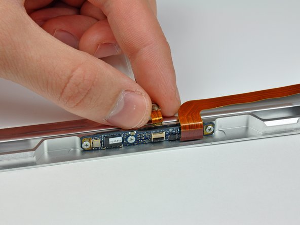
Be careful not to damage the ZIF cable retainer as you use the edge of a plastic opening tool to flip it up.
-
Pull the iSight cable out of its socket on the camera board.
-
-
Dieser Schritt ist noch nicht übersetzt. Hilf mit, ihn zu übersetzen!
-
First remove the strip of tape covering the iSight cable.
-
Next, peel the three orange antenna straps off the lower edge of the LCD.
-
Remove the two pieces of tape securing the display data cable to the LCD.
-
-
Dieser Schritt ist noch nicht übersetzt. Hilf mit, ihn zu übersetzen!
-
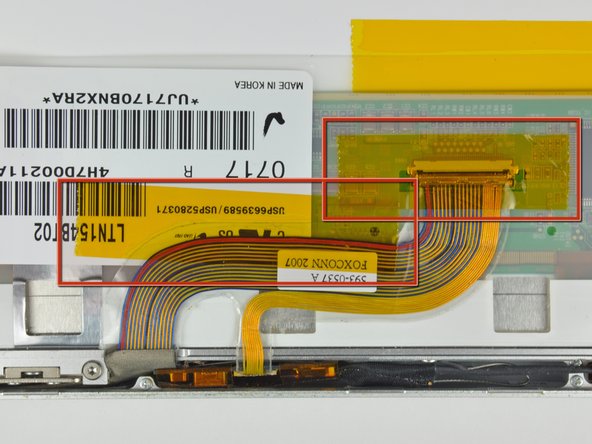
Disconnect the display data cable by pulling its connector toward the bottom edge of the display, away from the socket on the LCD.
-
-
Dieser Schritt ist noch nicht übersetzt. Hilf mit, ihn zu übersetzen!
-
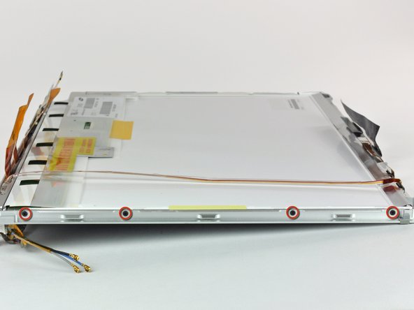
Remove the four 3 mm Phillips screws from each side of the display (eight screws total).
-
-
Dieser Schritt ist noch nicht übersetzt. Hilf mit, ihn zu übersetzen!
-
Do not simply pry on the edge of the frame as it is made of aluminum and can very easily bend!
-
Use the flat end of a spudger to gently lift one of the top corners of the LCD out of the front bezel.
-
-
Dieser Schritt ist noch nicht übersetzt. Hilf mit, ihn zu übersetzen!
-
Work your way along the top edge of the LCD, slowly prying the attached steel strip away from the front bezel.
-
-
Dieser Schritt ist noch nicht übersetzt. Hilf mit, ihn zu übersetzen!
-
Now that the top edge is free, slightly lift the LCD out of the front bezel for enough room to pry the steel strip along the lower edge of the LCD away from the front bezel.
-
Pry along the lower edge of the LCD until it is freed from the adhesive on the front bezel.
-
Avoid pulling the edge of the LCD unit from the screen. Be sure to insert the tool between the metal of the bezel and the metal of the LCD. If the adhesive is very strong, make a couple trips across the bottom edge to avoid applying too much pressure.
-
-
Dieser Schritt ist noch nicht übersetzt. Hilf mit, ihn zu übersetzen!
-
Lift the LCD out of the front bezel, minding any cables that may get caught.
-


Rückgängig: Ich habe diese Anleitung nicht absolviert.
139 weitere Nutzer:innen haben diese Anleitung absolviert.

7 Kommentare
I didn't have any trouble getting this apart - I used a small screwdriver from a jewelry repair kit (the set of six super small screwdrivers). I slide it in on the left front where it was open and slid it towards the IR thing. After that clip opened up I just slid it over towards the DVD drive... presto. Will update when I put this back together in a couple days. This guide should warn in the beginning to keep the screws identified in some way or you'll have a %*^! of time putting it back together.
I didn't have a spudger handy, but I got by just fine using an old credit card. Don't use a current one, as I dented up the edges pretty good in the process.
I've disassembled many a pc laptop without instructions, but macs are special ;) it was very helpful to have all the details spelled out for me. Thanks!
Be very carefull and bee patience. It´s very helpfull to have something like the ifixit magnetic project mat to keep the screws in order, otherwise you will have a hard time to put the parts together.