Diese Version enthält möglicherweise inkorrekte Änderungen. Wechsle zur letzten geprüften Version.
Was du brauchst
-
-
Benutze deine Finger und drücke bzw. ziehe die beiden Entriegelungslaschen vom Akku weg, und hebe den Akku aus dem Computer.
-
-
-
Entferne die drei identischen 2 mm Kreuzschlitzschrauben von der RAM Abdeckung.
-
Hebe die Abdeckung soweit hoch, dass du sie fassen kannst und ziehe sie weg vom Gehäuse zu dir hin.
-
-
-
Entferne die beiden 2,8 mm Kreuzschlitzschrauben im Akkufach in der Nähe der Verriegelung.
-
-
-
Entferne folgende sechs Schrauben:
-
Zwei 10 mm Torx T6 Schrauben auf jeder Seite des RAM- Einschubs.
-
Vier 14,5 mm Kreuzschlitzschrauben am Scharnier.
-
-
-
-
Entferne die vier 3,2 mm #00 Kreuzschlitzschrauben an der Seite mit den Anschlüssen.
-
-
-
Drehe den Computer um 90° und entferne die beiden 3,2 mm Kreuzschlitzschrauben auf der Rückseite des Computers.
-
-
-
Drehe den Computer weitere 90° und entferne die vier 3,2 mm Kreuzschlitzschrauben an der Seite des Computers.
-
-
-
Hebe das Gehäuse hinten hoch und arbeite dich dann mit den Fingern an den Seiten entlang nach vorne. Wenn die Seiten frei sind, dann bewege es auf und ab, sodass sich auch die Vorderkante ablöst.
-
Es gibt vier Kunststoffrasten über den DVD-Einschub und eine weitere links über dem Infrarotsensor. Diese Rasten lassen sich kaum lösen, ohne zu hebeln. Beim Zusammenbau sind sie auch wieder schwer einzurasten.
-
-
-
Trenne die Flachbandkabel des Trackpads und der Tastatur vom Logic Board ab, wobei du eventuell Klebebänder ablösen musst.
-
Entferne das Gehäuseoberteil.
-
-
Dieser Schritt ist noch nicht übersetzt. Hilf mit, ihn zu übersetzen!
-
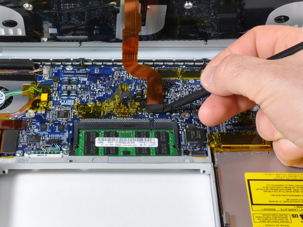
Disconnect the right fan cable from the logic board by placing a spudger beneath the cable and lifting up. Be sure to lift up on the right side as shown.
-
-
Dieser Schritt ist noch nicht übersetzt. Hilf mit, ihn zu übersetzen!
-
Remove the three silver T6 Torx screws securing the right fan to the logic board and lower case.
-
Lift the right fan up and carefully peel up the tape securing the fan to the heat sink as you go.
-
Rückgängig: Ich habe diese Anleitung nicht absolviert.
254 weitere Nutzer:innen haben diese Anleitung absolviert.
8 Kommentare
Excellent guide and pictures. I took the advise of several others and cleaned and lubed the fans, and had super results.
ok, so i started hearing a grinding noise from my computer and i thought it was just dirty and i went online to out how to do that. i came upon this website and found out that here you can find out about anything when i came to DIY. well the grinding noise was got worse and worse and found out that the right fan was the cause and it was a common issue to this version of the macbook pro. so ig ot the part and just put it in. its so quiet now as it was when i bought it. thank you for being here. i love this website. this is so user friendly and am already recommending this website to all my friends.
Thanks for the awesome feedback, nfleisher! Glad to hear your repair was a success.
Complete success, I downloaded a fan control app after I heard the grinding noise that I think most readers of this guide are familiar with. My fan was dropping into the 200rpm range and I had placed a box fan underneath the computer to keep the thing cool while I waited for the new fan unit to arrive. The guide was straightforward and pointed out a few of the problem areas that I might not have noticed without the prior heads up. The one addition that my IT friend pointed out to me is to make sure not to put the screws into the wrong holes during reassembly of step 5. There are two holes on either side of the DVI port and apparently once you mistakenly drop a screw into one of those holes its gone for good. Thank you so much, I could not have done this without this site.
Your guides are amazing! I printed out the PDF, punched tiny holes on the red circles to place removed screws, and just followed along. 10 minutes later, POOF! No more screeching fan, and all the screws went back where they belong! Awesome!


