Diese Version enthält möglicherweise inkorrekte Änderungen. Wechsle zur letzten geprüften Version.
Was du brauchst
-
-
Ziehe mit deinen Fingern beide Laschen vom Akku weg und hebe den Akku aus dem Computer heraus.
-
-
-
Entferne die drei identischen Kreuzschlitzschrauben von der RAM-Abdeckung.
-
-
-
Hebe die Abdeckung gerade genug an, um sie gut greifen zu können, und ziehe sie zu dir hin vom Gehäuse weg.
-
-
-
Entferne die beiden Kreuzschlitzschrauben im Akkufach in der Nähe der Verriegelung.
-
-
-
Entferne die folgenden 6 Schrauben:
-
Zwei 10 mm T6 Torx-Schrauben auf beiden Seiten des RAM-Steckplatzes.
-
Vier 14,5 mm Kreuzschlitzschrauben entlang des Scharniers.
-
-
-
Entferne die vier Kreuzschlitzschrauben an der Seite des Computers mit den Anschlüssen.
-
-
-
Drehe den Computer um 90 Grad und entferne die beiden Kreuzschlitzschrauben auf der Rückseite des Computers.
-
-
-
Drehe den Computer erneut um 90 Grad und entferne die vier Kreuzschlitzschrauben an der Seite des Computers.
-
-
-
Hebe das Gehäuse an der Rückseite an und fahren Sie mit den Fingern an den Seiten entlang, um das Gehäuse zu lösen.
-
Sobald die Seiten abgelöst sind, musst du das Gehäuse möglicherweise auf und ab bewegen, um die Vorderseite des oberen Gehäuses zu lösen. Dieser Schritt kann recht knifflig sein. Über dem DVD-Laufwerk befinden sich 4 zurückgesetzte Laschen, die sich vertikal herausziehen lassen.
-
Beachte, dass sich die beiden kleinen Ausstülpungen an der linken Vorderseite des oberen Gehäuses beim Entfernen des oberen Gehäuses verbiegen können. Beim Wiedereinbau musst du sie möglicherweise zurückbiegen, damit sie in die Rillen im unteren Gehäuses passen.
-
-
-
Trenne das Flachbandkabel des Trackpads und der Tastatur vom Logic Board ab und entferne, falls nötig, das Klebeband.
-
Entferne das obere Gehäuse.
-
-
Dieser Schritt ist noch nicht übersetzt. Hilf mit, ihn zu übersetzen!
-
Disconnect the two antenna cables attached to the Airport Extreme card.
-
-
Dieser Schritt ist noch nicht übersetzt. Hilf mit, ihn zu übersetzen!
-
Deroute the Airport antenna cables from their channel in the left speaker.
-
-
Dieser Schritt ist noch nicht übersetzt. Hilf mit, ihn zu übersetzen!
-
Disconnect the iSight, inverter, and left fan cables from the logic board by gently pulling in the direction of each cable.
-
-
-
Dieser Schritt ist noch nicht übersetzt. Hilf mit, ihn zu übersetzen!
-
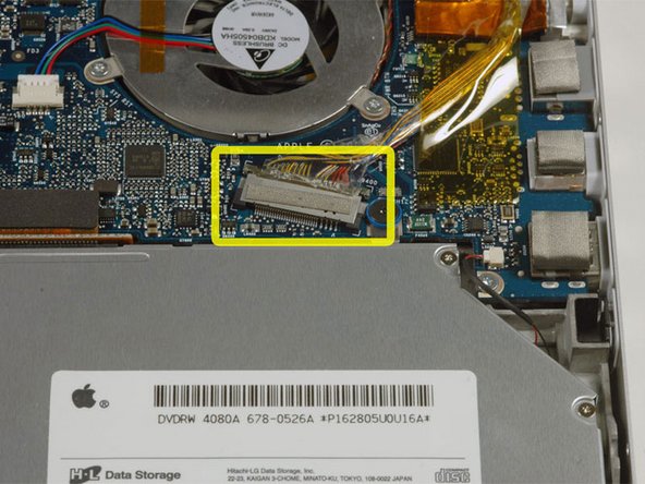
Disconnect the display data cable from the logic board.
-
-
Dieser Schritt ist noch nicht übersetzt. Hilf mit, ihn zu übersetzen!
-
Remove the silver T6 Torx screw securing the ground loop on the display data cable to the casing.
-
-
Dieser Schritt ist noch nicht übersetzt. Hilf mit, ihn zu übersetzen!
-
Support the display with one hand while removing the following 3 screws:
-
Two 9.5 mm silver T6 Torx screws with threads on only part of the shaft on the inside of the display hinges.
-
One 9.5 mm silver T6 Torx screw with threads on the entire shaft on the outside of the left hinge.
-
-
Dieser Schritt ist noch nicht übersetzt. Hilf mit, ihn zu übersetzen!
-
Grasp the display assembly on both sides and lift it up and out of the computer.
-
-
Dieser Schritt ist noch nicht übersetzt. Hilf mit, ihn zu übersetzen!
-
Remove the two 5 mm Phillips screws from the lower left and right corners of the display (two screws total).
-
-
Dieser Schritt ist noch nicht übersetzt. Hilf mit, ihn zu übersetzen!
-
Insert the flat end of a spudger perpendicular to the face of the display between the plastic strip attached to the rear bezel and the front bezel.
-
With the spudger still inserted, rotate it away from the display to separate the front and rear bezels.
-
Work along the left edge of the display until the rear bezel is evenly separated from the front bezel.
-
-
Dieser Schritt ist noch nicht übersetzt. Hilf mit, ihn zu übersetzen!
-
Insert the flat end of a spudger perpendicular to the face of the display between the plastic strip attached to the rear bezel and the front bezel.
-
With the spudger still inserted, rotate it away from the display to separate the front and rear bezels.
-
Work along the right edge of the display until the rear bezel is evenly separated from the front bezel.
-
-
Dieser Schritt ist noch nicht übersetzt. Hilf mit, ihn zu übersetzen!
-
Insert the flat end of a spudger between the front bezel and the plastic strip attached to the rear bezel near the screw holes at the bottom corners of the display.
-
Rotate your spudger toward the rear bezel to separate it from the front bezel.
-
If necessary, enlarge the gap between the lower edge of the rear bezel and the clutch cover until the two components are completely separated.
-
-
Dieser Schritt ist noch nicht übersetzt. Hilf mit, ihn zu übersetzen!
-
Lift the rear bezel by its bottom edge and rotate it away from the display assembly to separate the top edge.
-
Remove the rear display bezel from the display assembly.
-
-
Dieser Schritt ist noch nicht übersetzt. Hilf mit, ihn zu übersetzen!
-
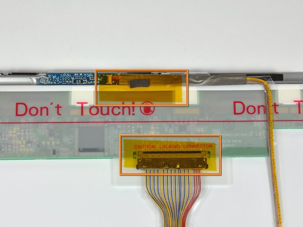
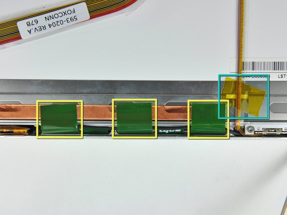
Remove the pieces of yellow kapton tape from the bottom left corner of the display.
-
Remove the pieces of tape securing the display data cable and camera cable to the display.
-
Peel the three green antenna ground straps off the copper tape along the bottom edge of the LCD.
-
Remove the piece of tape securing the camera cable to the LCD.
-
-
Dieser Schritt ist noch nicht übersetzt. Hilf mit, ihn zu übersetzen!
-
Carefully peel the camera cable off the foam tape along the top edge of the LCD.
-
-
Dieser Schritt ist noch nicht übersetzt. Hilf mit, ihn zu übersetzen!
-
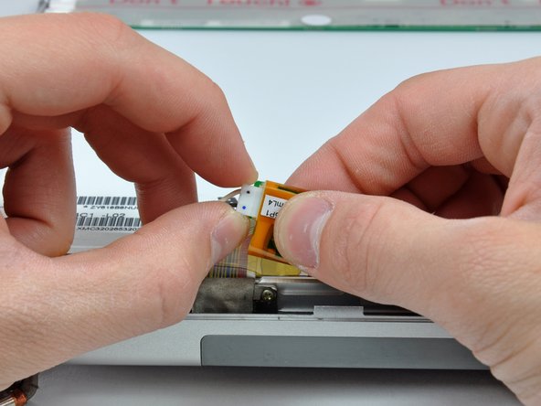
Use the tip of a spudger and carefully flip the ZIF connector bar up to release the before the camera cable.
-
Gently pull the camera cable away from its socket on the camera board.
-
-
Dieser Schritt ist noch nicht übersetzt. Hilf mit, ihn zu übersetzen!
-
Pull the display data cable connector away from its socket on the LCD.
-
-
Dieser Schritt ist noch nicht übersetzt. Hilf mit, ihn zu übersetzen!
-
Remove the four black Phillips screws along the left and right edges of the display (eight screws total).
-
-
Dieser Schritt ist noch nicht übersetzt. Hilf mit, ihn zu übersetzen!
-
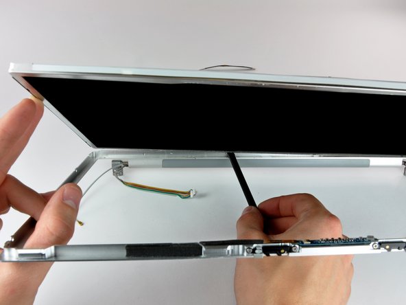
Use the flat end of a spudger to gently lift one of the top corners of the LCD out of the front bezel.
-
-
Dieser Schritt ist noch nicht übersetzt. Hilf mit, ihn zu übersetzen!
-
Work your way along the top edge of the LCD, slowly prying the attached steel strip away from the front bezel.
-
-
Dieser Schritt ist noch nicht übersetzt. Hilf mit, ihn zu übersetzen!
-
Now that the top edge is free, slightly lift the LCD out of the front bezel for enough room to pry the steel strip along the lower edge of the LCD away from the front bezel.
-
Pry along the lower edge of the LCD until it is freed from the adhesive on the front bezel.
-
-
Dieser Schritt ist noch nicht übersetzt. Hilf mit, ihn zu übersetzen!
-
Lift the inverter out of the clutch cover.
-
Disconnect the LCD backlight connector from its socket on the inverter board.
-
-
Dieser Schritt ist noch nicht übersetzt. Hilf mit, ihn zu übersetzen!
-
Lift the LCD out of the front bezel, minding any cables that may get caught.
-
-
Dieser Schritt ist noch nicht übersetzt. Hilf mit, ihn zu übersetzen!
-
Reconnect the following connectors back in their respective sockets on the logic board:
-
Camera connector cable
-
Inverter cable
-
Left fan
-
Display data cable
-
-
Dieser Schritt ist noch nicht übersetzt. Hilf mit, ihn zu übersetzen!
-
Connect the display data cable and the inverter cable connector back into their respective sockets on the original LCD assembly.
-
-
Dieser Schritt ist noch nicht übersetzt. Hilf mit, ihn zu übersetzen!
-
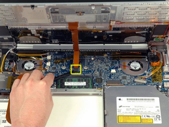
Use a spudger to re-seat the trackpad/keyboard ribbon cable connector to its socket on the logic board.
-
Carefully realign the upper case over the lower case.
-
-
Dieser Schritt ist noch nicht übersetzt. Hilf mit, ihn zu übersetzen!
-
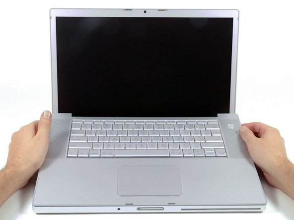
Connect an external USB mouse to your MacBook Pro.
-
Power up the MacBook Pro and boot into the OS.
-
Carefully lift the upper case and use a spudger to pry the trackpad/keyboard ribbon cable up off the logic board. Remove the upper case from the computer.
-
Use your external mouse to select the "Sleep" option from the Apple menu.
-
Make sure that the sleep light is pulsing before continuing.
-
-
Dieser Schritt ist noch nicht übersetzt. Hilf mit, ihn zu übersetzen!
-
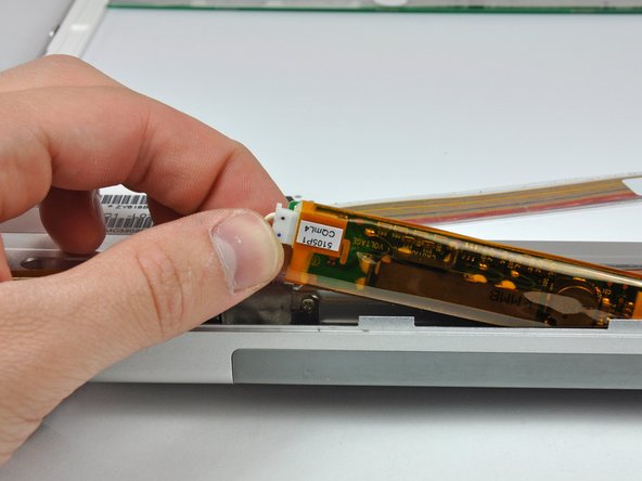
Disconnect the display data cable and inverter cable from the original LCD panel.
-
Connect the display data cable and inverter to the high definition LCD panel.
-
-
Dieser Schritt ist noch nicht übersetzt. Hilf mit, ihn zu übersetzen!
-
Use a spudger to re-seat the trackpad/keyboard ribbon cable connector to its socket on the logic board.
-
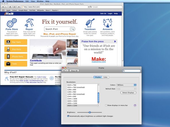
The MacBook Pro will now readjust itself to a resolution of 1920 x 1200!
-


Rückgängig: Ich habe diese Anleitung nicht absolviert.
6 weitere Nutzer:innen haben diese Anleitung absolviert.
