Einleitung
Use this guide to replace the AirPort/iSight Cable.
Was du brauchst
-
-
With the case closed, place the Unibody top-side down on a flat surface.
-
Depress the grooved side of the access door release latch enough to grab the free end. Lift the release latch until it is vertical.
-
-
-
The access door should now be raised enough to lift it up and out of the Unibody.
-
-
-
Grab the translucent plastic tab and pull the battery up and out of the Unibody.
-
If the latch is depressed it will lock the battery in place.
-
-
-
Remove the following eight screws securing the lower case to the chassis:
-
One 5.4 mm Phillips screw.
-
Three 14 mm Phillips screws.
-
Four 3.5 mm Phillips screws.
-
-
-
Disconnect the camera cable by pulling the male end straight away from its socket toward the optical drive opening.
-
Deroute the camera data cable from the channel in the optical drive.
-
-
-
Remove the two Phillips screws securing the camera cable bracket to the upper case.
-
Seperate the camera cable bracket from the camera cable and remove it from the computer.
-
-
-
Grab the plastic pull tab secured to the LVDS cable lock and rotate it toward the DC-in side of the computer.
-
Pull the LVDS connector straight away from its socket.
-
-
-
Remove the 7 mm Phillips screw from the LVDS cable bracket.
-
Lift the LVDS cable bracket out of the upper case.
-
-
-
Remove the two outer 6 mm Torx screws securing each side of the display to the upper case (four screws total).
-
-
-
Open your MacBook Pro so the display is perpendicular to the upper case.
-
Place your opened MacBook Pro on a table as pictured.
-
While holding the display and upper case together with your other hand, remove the 6 mm Torx screw from the lower display bracket.
-
-
-
Remove the last remaining 6 mm Torx screw securing the display to the upper case.
-
-
-
Grab the upper case with your right hand and rotate it slightly toward the top of the display so the upper display bracket clears the edge of the upper case.
-
Rotate the display slightly away from the upper case.
-
Lift the display away from the upper case, minding any brackets or cables that may get caught.
-
-
-
-
Before starting, be sure to clean the display glass with lint-free cloth moistened with a mild solution; it will make the suction cup adhere better, and will make checking for dust on reassembly easier
-
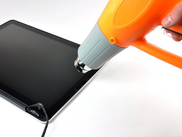
With the heat gun set to low, start by heating the outer black border near the upper right corner of the glass panel.
-
-
-
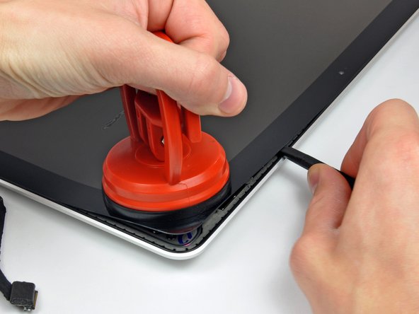
With the panel sufficiently heated, fasten a heavy-duty suction cup near the upper right corner of the display glass.
-
Slowly and gently pull the corner of the display glass up off the display assembly.
-
-
-
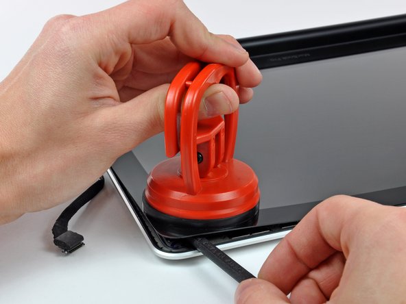
Gently lift the corner of the display glass enough to insert a spudger between it and the display assembly.
-
Use the flat end of a spudger to gently pry up the adhesive securing the front glass to the display.
-
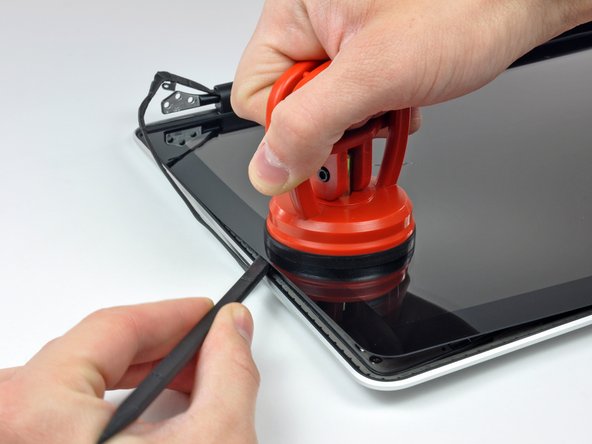
Pry up the glass panel a few inches away from the upper right corner along the top and right edges of the display.
-
-
-
Use a heat gun to soften the adhesive under the black strip along the right side of the front glass panel.
-
Attach a suction cup along the right side of the front glass panel.
-
Pull up on the glass panel while you use the flat end of a spudger to separate it from the rest of the display assembly.
-
Continue working along the right edge of the front display glass until it is separated from the display.
-
-
-
Use your heat gun to soften the adhesive under the black strip along the top edge of the glass display panel.
-
Attach a suction cup near the top edge of the glass display panel and use it to pull the glass panel up off the display.
-
Work along the top edge of the glass panel, carefully using the flat end of a spudger to separate the adhesive if necessary.
-
-
-
Use a heat gun to soften the adhesive under the black strip near the upper left corner of the glass display panel.
-
Attach a suction cup near the upper left corner of the glass display panel.
-
Pull up on the suction cup and use the flat end of a spudger to carefully pry the glass display panel out of the display assembly.
-
-
-
Use a heat gun to soften the adhesive under the black strip along the left side of the front glass panel.
-
Attach a suction cup along the left side of the front glass panel.
-
Pull up on the glass panel while you use the flat end of a spudger to separate it from the rest of the display assembly.
-
Continue working along the left edge of the front display glass until it is separated from the display.
-
-
-
Now that the top, left, and right edges of the glass are free from the display, slowly lift the top edge of the glass panel and gently rotate it out of the display.
-
-
-
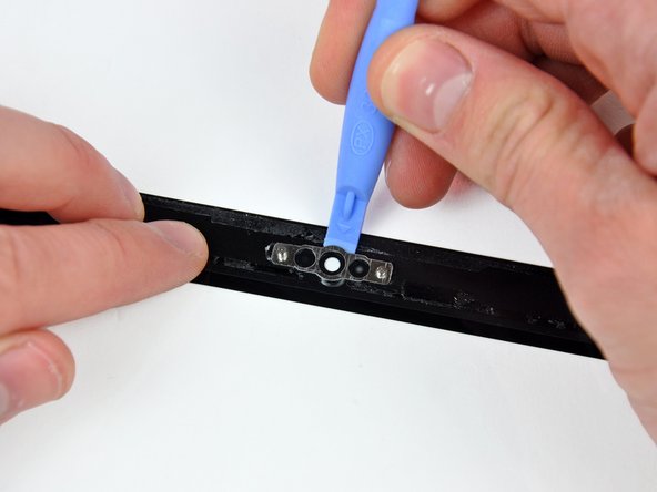
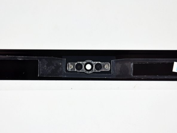
Insert the edge of a plastic opening tool between the display glass and the camera bracket, and run it around the camera bracket to separate it from the display glass.
-
-
-
To reconnect the cable, first use the tip of a spudger to remove the piece of foam tape over the camera cable ZIF socket.
-
Use the tip of a spudger to flip up the ZIF cable retainer on the camera cable socket.
-
Insert the camera cable into its socket on the camera board and use the tip of a spudger to snap down the ZIF cable retainer, locking the cable in place.
-
-
-
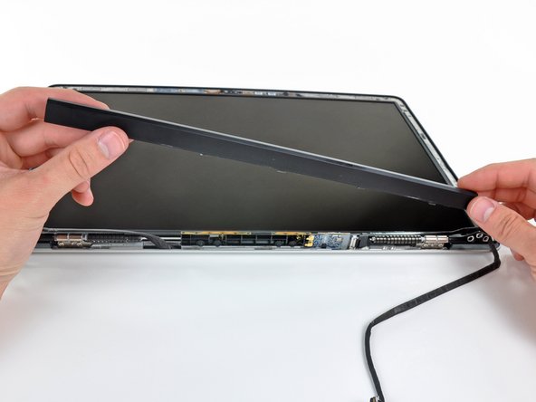
Starting at its far left end, rock the clutch cover along its long axis while pulling it away from the clutch hinge.
-
Working from right to left, carefully continue to release and lift the clutch along the lower edge of the display assembly.
-
Lift the clutch cover up off the front bezel and set it aside.
-
-
-
Remove the six 2.9 mm Phillips screws securing the LCD panel to the front bezel.
-
-
-
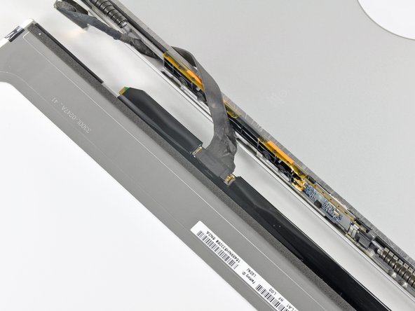
Pull the LCD toward the top edge of the display to slide the circuitry along its lower edge out of the recess in the aluminum display assembly.
-
-
-
Peel the piece of tape covering the display data cable connector away from the edge closest to the LCD.
-
-
-
Use the tip of a spudger to flip up the thin steel retaining clip securing the display data cable to its socket on the LCD.
-
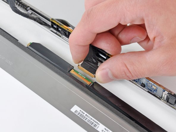
Pull the display data cable straight away from its socket on the LCD.
-
Lift the LCD out of the display assembly and set it aside.
-
-
-
Remove the 2.2 mm Phillips screw located near the bottom right corner securing the AirPort/iSight cable to the display assembly
-
-
-
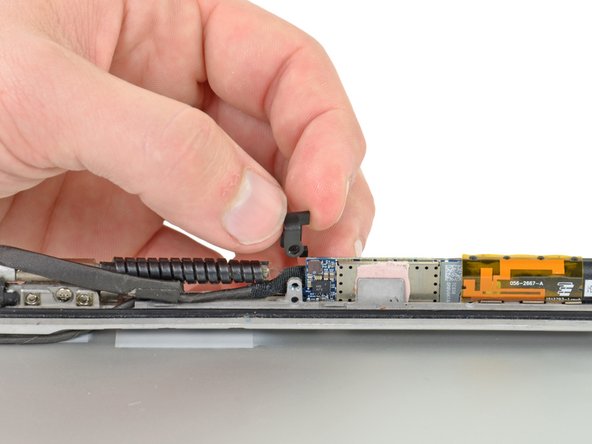
Remove the single 2.9 mm Phillips screw securing the plastic tab covering right edge of the inverter board.
-
Lift and remove the plastic tab up off the inverter board.
-
-
-
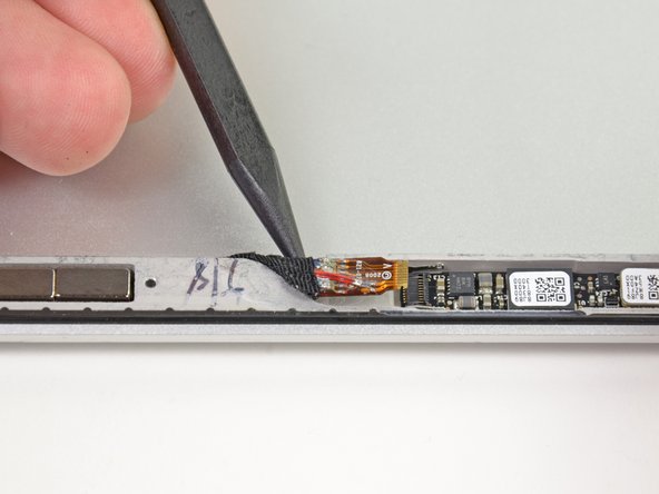
Use the tip of a spudger to flip up the retaining flap on the iSight ribbon cable ZIF socket on the iSight board.
-
Use the tip of a spudger to pull the iSight ribbon cable out of its socket.
-
-
-
Use the tip of a spudger to push the AirPort cable retaining lock away from its socket on the AirPort board.
-
Pull the AirPort cable straight out of its socket on the AirPort board.
-
-
-
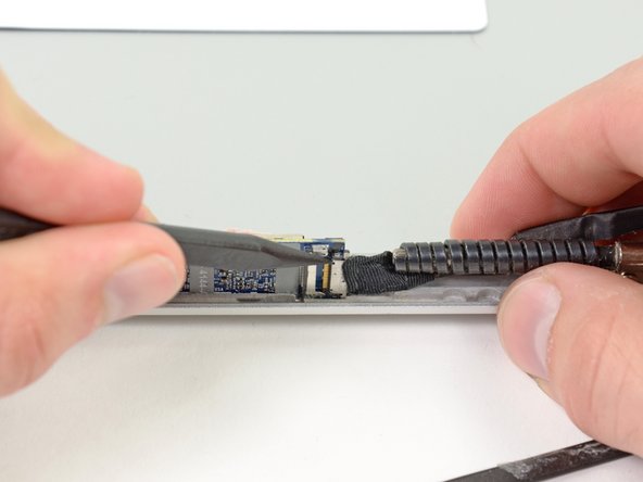
De-route the iSight ribbon cable from its channel near the top right corner of the display assembly.
-
Continue de-routing the AirPort/iSight cable from the right side of the display assembly.
-
-
-
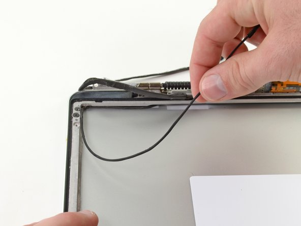
Carefully pull half of the AirPort/iSight cable through the opening located underneath the right hinge.
-
-
-
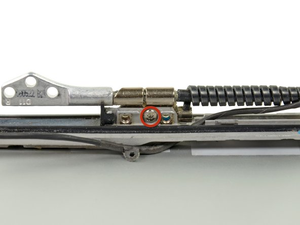
Remove three 2.5 mm T6 Torx screws securing the right hinge to the display assembly.
-
Remove the right hinge up off the display assembly.
-
-
-
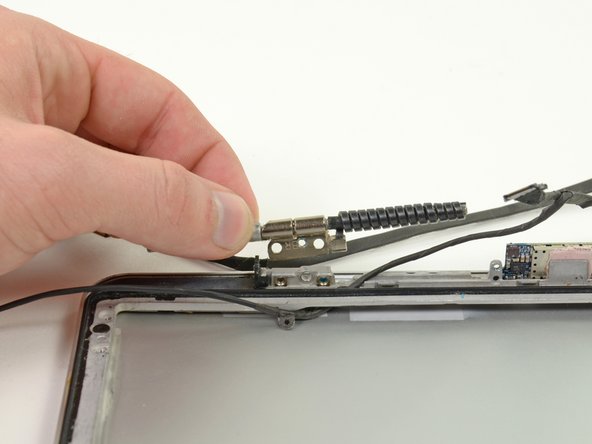
Pull the AirPort/iSight cable through the opening located near the bottom right corner of the display assembly.
-
Remove the AirPort/iSight cable from the display assembly.
-


To reassemble your device, follow these instructions in reverse order.
To reassemble your device, follow these instructions in reverse order.
Rückgängig: Ich habe diese Anleitung nicht absolviert.
12 weitere Personen haben diese Anleitung absolviert.
