Diese Version enthält möglicherweise inkorrekte Änderungen. Wechsle zur letzten geprüften Version.
Was du brauchst
-
-
Klappe das Display zu und platziere deinen Laptop umgedreht auf einer flachen Oberfläche.
-
Drücke die gerillte Seite der Entriegelunsvorrichtung nach unten und greife den herrausragenden Teil, um ihn nach oben ziehen zu können, bis er vertikal nach oben zeigt.
-
-
-
Fasse die durchsichtige Kunstofflasche an, ziehe den Akku hoch und aus dem Unibody heraus.
-
Wenn die Lasche eingedrückt ist, dann verriegelt sie den Akku.
-
-
-
Entferne die folgenden acht Kreuzschlitzschrauben, mit denen das untere Gehäuseunterteil befestigt ist:
-
Eine 5,4 mm Kreuzschlitzschraube
-
Drei 14 mm Kreuzschlitzschrauben
-
Vier 3,5 mm Kreuzschlitzschrauben
-
-
-
Hebe mit beiden Händen das Gehäuseunterteil vom oberen Gehäuse an und entferne es.
-
-
-
Entferne folgende fünf Kreuzschlitzschrauben, mit denen die Mittelwand am oberen Gehäuse befestigt ist:
-
Drei 10,5 mm Schrauben
-
Zwei 3,7 mm Schrauben
-
-
Dieser Schritt ist noch nicht übersetzt. Hilf mit, ihn zu übersetzen!
-
Remove the following six screws securing both the right fan and the left fan to the logic board:
-
Four 3.5 mm Phillips screws.
-
Two 3.2 mm Phillips screws.
-
-
Dieser Schritt ist noch nicht übersetzt. Hilf mit, ihn zu übersetzen!
-
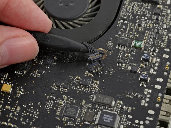
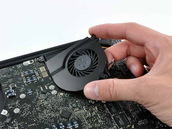
Use the tip of a spudger to lift the right fan connector straight up from its socket on the logic board.
-
Remove the right fan from the case.
-
-
Dieser Schritt ist noch nicht übersetzt. Hilf mit, ihn zu übersetzen!
-
Use the tip of a spudger to lift the left fan connector straight up from its socket on the logic board.
-
Remove the left fan from the case.
-
-
-
-
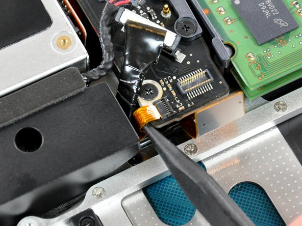
Entferne alle Klebereste vom Kamerakabel-Anschluss.
-
Trenne das Kamerakabel, indem du den Stecker aus der Buchse ziehst, allerdings nicht nach oben, sondern parallel zum Logic Board.
-
-
-
Heble den Anschluss des optischen Laufwerks mit einem Spudger vorsichtig von der Buchse auf dem Logic Board.
-
-
-
Heble den Subwoofer-Anschluss mit dem flachen Endes eines Spatels aus der Buchse auf dem Logic Board.
-
-
Dieser Schritt ist noch nicht übersetzt. Hilf mit, ihn zu übersetzen!
-
Use the flat end of a spudger to pry the silver-colored hard drive cable connector straight up out of its socket on the logic board.
-
-
Dieser Schritt ist noch nicht übersetzt. Hilf mit, ihn zu übersetzen!
-
Use a spudger to pry the trackpad connector straight up out of its socket on the logic board.
-
-
Dieser Schritt ist noch nicht übersetzt. Hilf mit, ihn zu übersetzen!
-
Using the tip of a spudger, flip up the IR/sleep LED ribbon cable retaining flap.
-
Pull the IR/sleep LED ribbon cable straight out of its socket.
-
-
Dieser Schritt ist noch nicht übersetzt. Hilf mit, ihn zu übersetzen!
-
Use a spudger to pry the battery indicator light connector straight up out of its socket on the logic board.
-
-
Dieser Schritt ist noch nicht übersetzt. Hilf mit, ihn zu übersetzen!
-
Using the tip of a spudger, flip up the keyboard ribbon cable retaining flap.
-
Pull the keyboard ribbon cable straight out of its socket.
-
-
Dieser Schritt ist noch nicht übersetzt. Hilf mit, ihn zu übersetzen!
-
Using the tip of a spudger, flip up the express card cage ribbon cable retaining flap.
-
Pull the express card cage ribbon cable straight out of its socket.
-
-
Dieser Schritt ist noch nicht übersetzt. Hilf mit, ihn zu übersetzen!
-
Using the flat end of a spudger, pry the microphone cable connector straight up out of its socket on the logic board.
-
-
Dieser Schritt ist noch nicht übersetzt. Hilf mit, ihn zu übersetzen!
-
Grab the plastic pull tab secured to the display data cable lock and rotate it toward the DC-in side of the computer.
-
Pull the display data cable connector straight away from its socket.
-
-
Dieser Schritt ist noch nicht übersetzt. Hilf mit, ihn zu übersetzen!
-
Locate the keyboard backlight ribbon cable (near the left fan space).
-
Using the tip of a spudger, flip up the keyboard backlight ribbon cable retaining flap.
-
Pull the keyboard backlight ribbon cable straight out of its socket.
-
-
Dieser Schritt ist noch nicht übersetzt. Hilf mit, ihn zu übersetzen!
-
Remove seven 3.2 mm Phillips screws securing the logic board to the upper case.
-
-
Dieser Schritt ist noch nicht übersetzt. Hilf mit, ihn zu übersetzen!
-
Remove two 7 mm Phillips screws securing the DC-in board to the upper case.
-
-
Dieser Schritt ist noch nicht übersetzt. Hilf mit, ihn zu übersetzen!
-
Remove two 3.5 mm Phillips screws securing the bottom case clip to the upper case.
-
Lift the bottom case clip out of the upper case.
-
-
Dieser Schritt ist noch nicht übersetzt. Hilf mit, ihn zu übersetzen!
-
Carefully lift the logic board assembly from the left side and work it out of the upper case, minding the port side that may get caught during removal.
-
-
Dieser Schritt ist noch nicht übersetzt. Hilf mit, ihn zu übersetzen!
-
Lift the logic board enough to grab the battery connector and pull it straight away from its socket on the logic board.
-
Lift the logic board assembly out of the upper case.
-
-
Dieser Schritt ist noch nicht übersetzt. Hilf mit, ihn zu übersetzen!
-
Remove two 5 mm Phillips screws securing the left speaker to the logic board.
-
-
Dieser Schritt ist noch nicht übersetzt. Hilf mit, ihn zu übersetzen!
-
Use the flat end of a spudger to pry the left speaker connector up off the logic board.
-
-
Dieser Schritt ist noch nicht übersetzt. Hilf mit, ihn zu übersetzen!
-
Lift the left speaker assembly out of the logic board.
-
Deroute the microphone cable from the channel in the left speaker and use the tip of a spudger to dislodge the microphone from its housing within the left speaker.
-


Rückgängig: Ich habe diese Anleitung nicht absolviert.
9 weitere Nutzer:innen haben diese Anleitung absolviert.

Ein Kommentar
How do I get a mother board from ~ VIN, MacBook Pro (15 inch, Mid 2010)
Model Name: MacBook Pro
Model name: MacBookPro6,2
Processor name: Intel Core i5
Processor Speed: 2.4 GHz
Number of Processors: 1
Total number of cores: 2
L2 cache (per core): 256 KB
L3 cache: 3 MB
Memory: 8 GB
Processor Connection Speed: 4.8 GT / s
Boot ROM version: MBP61.0057.B11
SMC version (system): 1.58f17
Serial Number (system): W80460FKAGX
Hardware UUID: B75113BB-15D7-5E66-8407-029768AFA96D
Brushed Motion Sensor:
Here in Rio de Janeiro (Brazil) I can not find