Diese Version enthält möglicherweise inkorrekte Änderungen. Wechsle zur letzten geprüften Version.
Was du brauchst
-
-
Klappe das Display zu und platziere deinen Laptop umgedreht auf einer flachen Oberfläche.
-
Drücke die gerillte Seite der Entriegelunsvorrichtung nach unten und greife den herrausragenden Teil, um ihn nach oben ziehen zu können, bis er vertikal nach oben zeigt.
-
-
-
Fasse die durchsichtige Kunstofflasche an, ziehe den Akku hoch und aus dem Unibody heraus.
-
Wenn die Lasche eingedrückt ist, dann verriegelt sie den Akku.
-
-
-
Entferne die folgenden acht Kreuzschlitzschrauben, mit denen das untere Gehäuseunterteil befestigt ist:
-
Eine 5,4 mm Kreuzschlitzschraube
-
Drei 14 mm Kreuzschlitzschrauben
-
Vier 3,5 mm Kreuzschlitzschrauben
-
-
-
Hebe mit beiden Händen das Gehäuseunterteil vom oberen Gehäuse an und entferne es.
-
-
-
Entferne folgende fünf Kreuzschlitzschrauben, mit denen die Mittelwand am oberen Gehäuse befestigt ist:
-
Drei 10,5 mm Schrauben
-
Zwei 3,7 mm Schrauben
-
-
Dieser Schritt ist noch nicht übersetzt. Hilf mit, ihn zu übersetzen!
-
Remove the following six screws securing both the right fan and the left fan to the logic board:
-
Four 3.5 mm Phillips screws.
-
Two 3.2 mm Phillips screws.
-
-
Dieser Schritt ist noch nicht übersetzt. Hilf mit, ihn zu übersetzen!
-
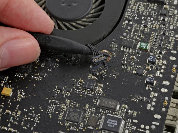
Use the tip of a spudger to lift the right fan connector straight up from its socket on the logic board.
-
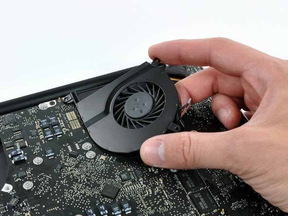
Remove the right fan from the case.
-
-
Dieser Schritt ist noch nicht übersetzt. Hilf mit, ihn zu übersetzen!
-
Use the tip of a spudger to lift the left fan connector straight up from its socket on the logic board.
-
Remove the left fan from the case.
-
-
-
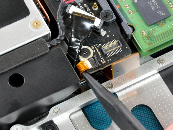
Entferne alle Klebereste vom Kamerakabel-Anschluss.
-
Trenne das Kamerakabel, indem du den Stecker aus der Buchse ziehst, allerdings nicht nach oben, sondern parallel zum Logic Board.
-
-
-
Heble den Anschluss des optischen Laufwerks mit einem Spudger vorsichtig von der Buchse auf dem Logic Board.
-
-
-
-
Heble den Subwoofer-Anschluss mit dem flachen Endes eines Spatels aus der Buchse auf dem Logic Board.
-
-
Dieser Schritt ist noch nicht übersetzt. Hilf mit, ihn zu übersetzen!
-
Use the flat end of a spudger to pry the silver-colored hard drive cable connector straight up out of its socket on the logic board.
-
-
Dieser Schritt ist noch nicht übersetzt. Hilf mit, ihn zu übersetzen!
-
Use a spudger to pry the trackpad connector straight up out of its socket on the logic board.
-
-
Dieser Schritt ist noch nicht übersetzt. Hilf mit, ihn zu übersetzen!
-
Using the tip of a spudger, flip up the IR/sleep LED ribbon cable retaining flap.
-
Pull the IR/sleep LED ribbon cable straight out of its socket.
-
-
Dieser Schritt ist noch nicht übersetzt. Hilf mit, ihn zu übersetzen!
-
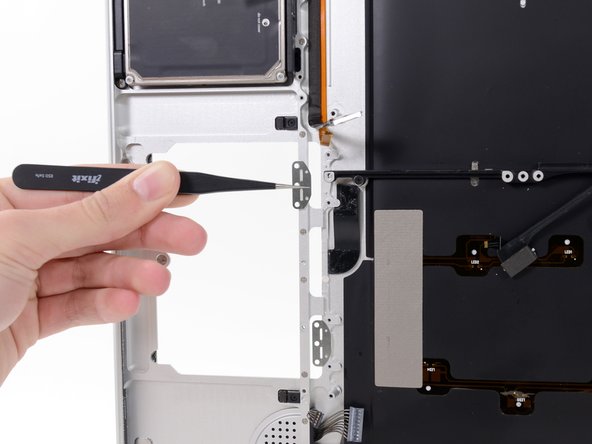
Use a spudger to pry the battery indicator light connector straight up out of its socket on the logic board.
-
-
Dieser Schritt ist noch nicht übersetzt. Hilf mit, ihn zu übersetzen!
-
Using the tip of a spudger, flip up the keyboard ribbon cable retaining flap.
-
Pull the keyboard ribbon cable straight out of its socket.
-
-
Dieser Schritt ist noch nicht übersetzt. Hilf mit, ihn zu übersetzen!
-
Using the tip of a spudger, flip up the express card cage ribbon cable retaining flap.
-
Pull the express card cage ribbon cable straight out of its socket.
-
-
Dieser Schritt ist noch nicht übersetzt. Hilf mit, ihn zu übersetzen!
-
Using the flat end of a spudger, pry the microphone cable connector straight up out of its socket on the logic board.
-
-
Dieser Schritt ist noch nicht übersetzt. Hilf mit, ihn zu übersetzen!
-
Grab the plastic pull tab secured to the display data cable lock and rotate it toward the DC-in side of the computer.
-
Pull the display data cable connector straight away from its socket.
-
-
Dieser Schritt ist noch nicht übersetzt. Hilf mit, ihn zu übersetzen!
-
Locate the keyboard backlight ribbon cable (near the left fan space).
-
Using the tip of a spudger, flip up the keyboard backlight ribbon cable retaining flap.
-
Pull the keyboard backlight ribbon cable straight out of its socket.
-
-
Dieser Schritt ist noch nicht übersetzt. Hilf mit, ihn zu übersetzen!
-
Remove seven 3.2 mm Phillips screws securing the logic board to the upper case.
-
-
Dieser Schritt ist noch nicht übersetzt. Hilf mit, ihn zu übersetzen!
-
Remove two 7 mm Phillips screws securing the DC-in board to the upper case.
-
-
Dieser Schritt ist noch nicht übersetzt. Hilf mit, ihn zu übersetzen!
-
Remove two 3.5 mm Phillips screws securing the bottom case clip to the upper case.
-
Lift the bottom case clip out of the upper case.
-
-
Dieser Schritt ist noch nicht übersetzt. Hilf mit, ihn zu übersetzen!
-
Carefully lift the logic board assembly from the left side and work it out of the upper case, minding the port side that may get caught during removal.
-
-
Dieser Schritt ist noch nicht übersetzt. Hilf mit, ihn zu übersetzen!
-
Lift the logic board enough to grab the battery connector and pull it straight away from its socket on the logic board.
-
Lift the logic board assembly out of the upper case.
-
-
Dieser Schritt ist noch nicht übersetzt. Hilf mit, ihn zu übersetzen!
-
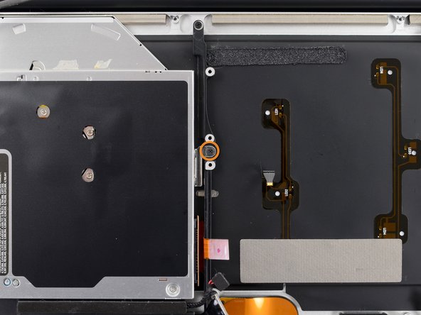
Deroute the camera data cable from its channel on the optical drive.
-
-
Dieser Schritt ist noch nicht übersetzt. Hilf mit, ihn zu übersetzen!
-
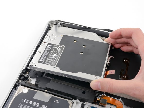
Remove the following three Phillips screws securing the optical drive to the upper case:
-
Two 2.5 mm Phillips screws.
-
One 3.5 mm Phillips screw.
-
Lift the optical drive out of the upper case.
-
-
Dieser Schritt ist noch nicht übersetzt. Hilf mit, ihn zu übersetzen!
-
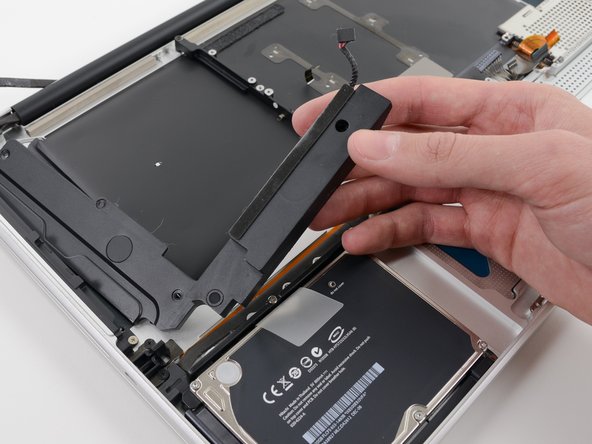
Remove the following four screws securing the subwoofer and right speaker to the upper case:
-
Two 3.2 mm Phillips screws.
-
One 2.6 mm Phillips screw.
-
One 5.0 mm Phillips screw.
-
Lift the subwoofer and right speaker assembly out of the upper case.
-
-
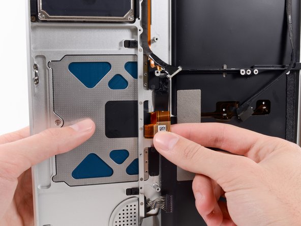
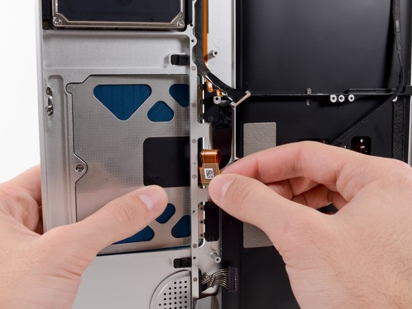
Dieser Schritt ist noch nicht übersetzt. Hilf mit, ihn zu übersetzen!
-
Insert the flat end of a spudger underneath the trackpad ribbon cable and gently peel it up from the adhesive securing it to the upper case.
-
-
Dieser Schritt ist noch nicht übersetzt. Hilf mit, ihn zu übersetzen!
-
Open your MacBook Pro and set it on a table as shown.
-
-
Dieser Schritt ist noch nicht übersetzt. Hilf mit, ihn zu übersetzen!
-
While holding the edge of the trackpad closest to the logic board with one hand, remove the six 1.3 mm Phillips screws securing the two brackets to the trackpad.
-
-
Dieser Schritt ist noch nicht übersetzt. Hilf mit, ihn zu übersetzen!
-
While holding the trackpad in place with your left hand, fold the top of the trackpad ribbon cable down with your right hand so that it fits through its slot in the upper case.
-
Feed the ribbon cable through the slot as you push the portion of the trackpad closest to the keyboard out of the upper case.
-
-
Dieser Schritt ist noch nicht übersetzt. Hilf mit, ihn zu übersetzen!
-
With the cable free, remove the trackpad from the upper case.
-
-
Dieser Schritt ist noch nicht übersetzt. Hilf mit, ihn zu übersetzen!
-
Remove the four 2.7 mm Phillips screws from the two trackpad bracket covers.
-


Rückgängig: Ich habe diese Anleitung nicht absolviert.
55 weitere Nutzer:innen haben diese Anleitung absolviert.

3 Kommentare
What size is the tri-wing screwdriver needed to adjust the trackpad on this model?