Einleitung
Diese Anleitung zeigt dir, wie du den Kühlkörper austauschen kannst.
Was du brauchst
-
-
Entferne die folgenden zehn Schrauben, mit denen das untere Gehäuse am oberen Gehäuse befestigt ist:
-
Sieben 3 mm Kreuzschlitzschrauben
-
Drei 13,5 mm Kreuzschlitzschrauben
-
-
-
Hebe das untere Gehäuse mit beiden Händen in der Nähe der Lüftungsöffnung an, damit sich die beiden Clips lösen, mit denen die beiden Gehäuseteile verbunden sind.
-
Entferne das untere Gehäuse und lege es zur Seite.
-
-
KaufenIn diesem Schritt verwendetes Werkzeug:P6 Pentalobe Screwdriver 2009 15" MacBook Pro Battery$5.49
-
Entferne die beiden 5-Punkt Pentalobe Schrauben an der Oberkante des Akkus.
Question: why do you remove the battery? According to Apple's official manual, this is not required (not for the mid-2009 and not for the mid-2010 15-inch MacBook Pro) - see pages 37 ff:
Zitat von alexkli:
Question: why do you remove the battery? According to Apple's official manual, this is not required (not for the mid-2009 and not for the mid-2010 15-inch MacBook Pro) - see pages 37 ff:
I'm interested by your experience.
Did you have removed the optical drive without removing the battery ?
I'm just in this step now and if it is possible I would proceed like you because removing the battery void the warranty (and there is a sticker).
Thanks in advance.
Looks like my note to step 3 appears on all repair guides that have the same step. I meant that in the context of the hard drive replacement only.
Did you have removed the optical drive without removing the battery ?
I haven't yet done anything, waiting for my MacBook Pro 15 inch mid-2010 to arrive.
I missed the notes and went ahead and purchased the 5 point driver for the battery before I realized it was not necessary.
I've edited the repair guide to remove the section on the battery, but I don't have the points to approve the changes.
Please note - the step about removing the battery is part of a pre-requisite guide, that is used for many of the guides, most that do require removal of the battery. Also, working inside a disassembled laptop with the battery still connected risks damaging/shorting out very expensive parts.
Absolutely. To be clear -- ALL of the above discussion is ONLY in reference to replacing the hard drive.
I replaced a hard drive in a MacBook Pro of an earlier model than this without removing the battery. The hard drive wasn't right. It only worked at about half speed, and I had to replace it once more. The second time I removed the battery and all went well. The recommendation by the iFixit staff to remove the battery before working on electronic equipment is a good one.
What is the size of those screws... I have rounded off the socket on mine and would like to replace them.
I measured the screw size, using a micrometer, its about 1.523mm in diameter and 3.186mm in length. Not sure what screw size that is. They are not easily available I guess, unless someone is selling used ones on ebay
-
-
-
Biege die Ausbuchtung am Aufkleber "Warning: Do not remove the battery" mit der Spudgerspitze hoch, um die dritte Pentalobe Schraube darunter zu entfernen.
-
-
-
Hebe den Akku an seiner Plastiklasche hoch und schiebe ihn von der langen Kante des oberen Gehäuses weg.
My T6 (appears to be same screw driver you have - $6 on amazon for 20piece set) did NOT fit int he battery screws...not sure if I had the wrong screws or what, but I went ahead w/o battery steps and it was pretty easy.
I also noticed that the new SDD (from crucial) didn't have the 4 screws, so I had to move those off the old HD and onto the new one.
Just had the same issue: T6 does not fit the battery screws ;-( ... but with a little bit more preassure it was possible to remove the screws.
-
-
-
Kippe den Akku soweit nach hinten, dass du an den Akkukabelstecker herankommst.
-
Ziehe den Akkukabelstecker aus seinem Anschluss auf dem Logic Board und entferne den Akku aus dem oberen Gehäuse.
-
Wenn du einen neuen Akku einbaust, solltest du ihn nach dem Einbau kalibrieren.
-
-
-
Löse den Stecker des Lüfters mit dem Spudger vom Anschluss auf dem Logic Board.
-
-
-
Entferne die drei Torx T6 Schrauben, mit denen der linke Lüfter am Logic Board befestigt ist.
-
Hebe den Lüfter aus dem oberen Gehäuse.
Top left screw in this picture isn't a torx screw, and should be left in place. The screw you want is a bit further down than the one circled.
Good catch! It's fixed now.
-
-
-
Trenne den Stecker des linken Lüfters mit dem flachen Ende des Spudgers vom Logic Board ab.
I didn't understand the description of the step to remove the fan connectors and I broke them both off. However! If anyone else does this, don't panic, the soldered connections are not electrical; they're just there to secure the fan connector. If you have the equipment you may be able to solder them back on, but I just put the whole thing back together - carefully sliding the jack back over the pins - and held it down with polyimide tape. I am using my Macbook Pro right now and the fans are definitely working.
For my Mid 2009 Macbook Pro, I only had one fan, so didn't have to do step 9 and 10.
-
-
-
Entferne die drei Torx T6 Schrauben, mit denen der linke Lüfter am Logic Board befestigt ist.
-
Hebe den linken Lüfter aus dem oberen Gehäuse heraus.
For my Mid 2009 Macbook Pro, I only had one fan, so didn't have to do step 9 and 10.
-
-
-
-
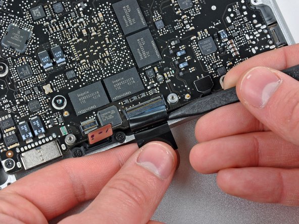
Halte den Halter des Kabels an einem Ende mit dem Finger nach unten, hebe das andere Ende ein wenig mit der Spudgerspitze hoch und drehe es vom Kamerakabelstecker weg.
-
Ziehe das Kamerakabel gerade aus seinem Anschluss auf dem Logic Board heraus.
I’ve tried to clear things up in a pending modification, since I also had problems getting the point of this step. Hope it helps.
The “strip” is the shiny black thing on the photo. The tip of the spudger is “pointing” at it on the photo. In fact it is already pushing the “strip” out of the way to be able to pull out the connector.
I finally got my system back together & running so much cooler after removing, cleaning the heat sink & repasting the CPU die & the two GPU dies. But working backward from this step to put it back together was most arduous: neither camera nor WiFi/Bluetooth worked when I first put the system back together. This is because it was hard to gauge that this connector was indeed back together and hold it so, based on 12 year-old fabric-padded adhesive alone. In the end, I checked that no pins in the connector were bent, guided them in as firmly as a flat spudger (not my hand, which twisted the cable at an angle) would allow, held it in the connector bay with electrical tape, put the fabric cushion back on top of that, and electrical taped across the cushion, between the connector bay and the cable. Phew! After tons of trial and error, put the system back together & both WiFi/Bluetooth and the camera work again!
-
-
-
Heble den Stecker am Kabel zum optischen Laufwerk mit dem flachen Ende des Spudgers vom Logic Board weg.
-
-
-
Heble den Stecker zum Tieftöner mit dem flachen Ende des Spudgers gerade aus seinem Anschluss heraus.
-
-
-
Heble den Stecker am Kabel zur Festplatte/Infrarotsensor mit dem flachen Ende des Spudgers vom Logic Board weg.
-
-
-
Entferne die beiden 1,5 mm Kreuzschlitzschrauben, mit denen die Kabelabdeckung am Logic Board befestigt ist.
-
Hebe die Kabelabdeckung aus dem oberen Gehäuse heraus.
-
-
-
Heble den Stecker am Flachbandkabel zum Trackpad mit dem Spudger vom Logic Board weg.
-
-
-
Klappe den Sicherungsbügel am ZIF-Anschluss des Tastaturkabels mit dem Fingernagel hoch. Die Verriegelungsklappe befindet sich gegenüber vom Anschluss im Vergleich zum Tastaturkabel. Schiebe deinen Fingernagel darunter und hebe sie senkrecht hoch.
-
Schiebe das Tastaturkabel mit der Spudgerspitze aus seinem Anschluss heraus.
-
-
-
Heble den Stecker am Flachbandkabel zur Akkuanzeige mit dem Spudger vom Logic Board hoch.
-
-
-
Entferne die einzelne 7 mm Kreuzschlitzschraube, welche den Halter des Displaydatenkabels am oberen Gehäuse befestigt.
-
Entferne den Halter des Displaydatenkabels vom oberen Gehäuse.
-
-
-
Fasse die Plastikzuglasche an der Verriegelung des Displaydatenkabels und drehe sie zur Seite mit der Gleichspannungsversorgung am Computer.
-
-
-
Klappe den Sicherungsbügel am Flachbandkabel der Tastaturbeleuchtung mit der Spudgerspitze hoch.
-
Ziehe das Flachbandkabel der Tastaturbeleuchtung gerade aus seinem Anschluss heraus.
-
-
-
Entferne folgende Schrauben:
-
Sieben 3,3 mm Torx T6 Schrauben, mit denen das Logic Board am oberen Gehäuse befestigt ist.
-
Zwei 8 mm Torx T6 Schrauben, mit denen die Platine der Gleichspannungsversorgung am oberen Gehäuse befestigt ist.
-
-
-
Hebe das Logic Board sorgfältig an der linken Seite an und hole es aus dem oberen Gehäuse heraus. Achte dabei auf die Seite mit den Anschlüssen, die sich möglicherweise verfangen können.
-
-
-
Hebe das Board soweit an, dass du mit einem Spudger das Mikrofon vom oberen Gehäuse hebeln kannst.
-
Schiebe das Logic Board von den Anschlussöffnungen weg und hebe die Einheit aus dem oberen Gehäuse heraus.
-
-
-
Schiebe das Logic Board von den Anschlussöffnungen weg und hebe die Einheit aus dem oberen Gehäuse heraus.
-
-
-
Lege das Logic Board auf eine weiche flache Oberfläche, so dass der Kühlkörper nach oben zeigt.
-
-
-
Entferne die acht Kreuzschlitzschrauben, mit denen der Kühlkörper am Logic Board befestigt ist.
-
Hebe den Kühlkörper vorsichtig vom Logic Board ab.
-
Beim Einbau des Kühlkörpers hilft dir unsere Anleitung dabei, neue Wärmeleitpaste aufzutragen.
-


Um dein Gerät wieder zusammenbauen, folge den Schritten in umgekehrter Reihenfolge.
Um dein Gerät wieder zusammenbauen, folge den Schritten in umgekehrter Reihenfolge.
Rückgängig: Ich habe diese Anleitung nicht absolviert.
25 weitere Nutzer:innen haben diese Anleitung absolviert.
Besonderer Dank geht an diese Übersetzer:innen:
100%


Diese Übersetzer:innen helfen uns, die Welt zu reparieren! Wie kann ich mithelfen?
Hier starten ›

3 Kommentare
I did use a common flathead screwdriver for 5-point and 6-point screws. It' worked well.
Thank you very much for this guide !
I just used this guide to pull out my logic board and clean about 6 years of dust out. Also was able to take apart the fans and throw a little bit of wd40 on the axels. We are back to whisper quiet computing and about 10-15 degrees cooler.
I messed up something because the machine doesn't turn on (
May be helpful to have more distinct colors to identify the different screws.
Victor Caamano - Antwort