Diese Version enthält möglicherweise inkorrekte Änderungen. Wechsle zur letzten geprüften Version.
Was du brauchst
-
-
Drücke mit deinen Fingern die beiden Laschen der Haltevorrichtung, um den Akku zu lösen und aus dem Computer zu entfernen.
-
-
-
Entferne die vier identischen 3,4 mm Kreuzschlitzschrauben von der Speicherabdeckung. Diese Schrauben haben einen Schraubenkopf mit einem Durchmesser von 4 mm im Gegensatz zu denen mit einem Durchmesser von 3 mm am Gehäuse selbst.
-
-
-
Hebe die Abdeckung gerade so weit hoch, dass du sie fassen kannst, um sie dann auf dich zu zu schieben und so aus dem Gehäuse zu ziehen.
-
-
-
Entferne die drei Kreuzschlitzschrauben im Akkufach in der Nähe der Verriegelung. Apple war so nett, diese Schrauben in einem leichten Winkel zu neigen, damit sie sich leichter entfernen lassen. Beim A1261 haben diese Schrauben Köpfe mit einem Durchmesser von 4 mm und nicht wie bei den Gehäuseschrauben 3 mm.
-
-
-
Entferne die folgenden sechs Schrauben:
-
Zwei 14,5 mm T6 Torx Schrauben auf beiden Seiten des RAM-Steckplatzes.
-
Vier 3,4 mm Kreuzschlitzschrauben entlang des Scharniers.
-
-
-
Entferne die vier 3,4 mm Kreuzschlitzschrauben an der Seite des Computers mit den Anschlüssen.
-
-
-
Drehe den Computer um 90 Grad und entferne die beiden Kreuzschlitzschrauben auf der Rückseite des Computers.
-
-
-
Drehe den Computer erneut um 90 Grad und entferne die vier Kreuzschlitzschrauben an der Seite des Computers.
-
-
-
Hebe die Rückseite des Gehäuses an und fahre mit den Fingern an den Seiten entlang, um das Gehäuse zu lösen. Sobald du die Seiten gelöst hast, musst du das Gehäuse möglicherweise auf und ab bewegen, um die Vorderseite des oberen Gehäuses abzulösen.
-
-
-
Trenne das Flachbandkabel des Trackpads und der Tastatur vom Logic Board ab.
-
Entferne das obere Gehäuse.
-
-
Dieser Schritt ist noch nicht übersetzt. Hilf mit, ihn zu übersetzen!
-
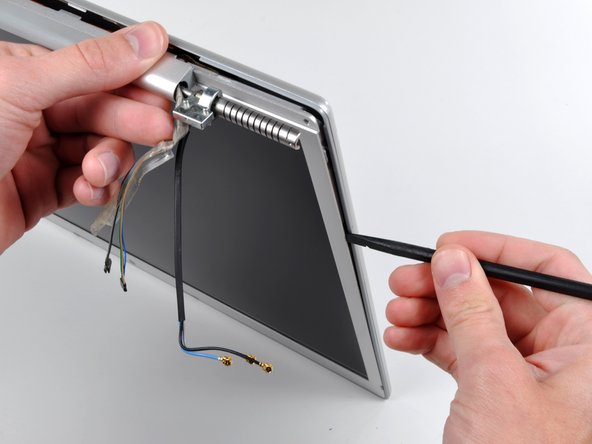
Disconnect the two antenna cables from the AirPort Extreme card, the iSight and inverter cables from the left side of the logic board, and the display data cable from the right side of the logic board. Be careful to slide the connectors as they may become damaged otherwise.
-
Carefully peel the iSight and inverter cables off the top of the left fan and de-route the AirPort antenna cables from the channel in the left speaker.
-
-
Dieser Schritt ist noch nicht übersetzt. Hilf mit, ihn zu übersetzen!
-
Remove the ten silver T6 Torx screws securing the display (five on each side-take note that the inside screws on both sides are longer with a thinner head).
-
-
-
Dieser Schritt ist noch nicht übersetzt. Hilf mit, ihn zu übersetzen!
-
Grasp the display assembly on both sides and lift it up and out of the computer.
-
-
Dieser Schritt ist noch nicht übersetzt. Hilf mit, ihn zu übersetzen!
-
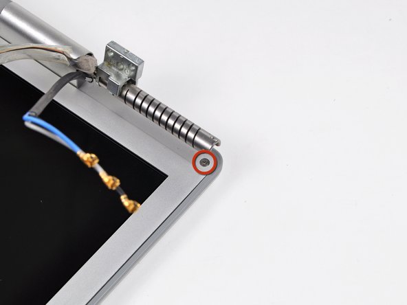
Remove the Phillips screws from the lower left and right corners of the display (two screws total).
-
-
Dieser Schritt ist noch nicht übersetzt. Hilf mit, ihn zu übersetzen!
-
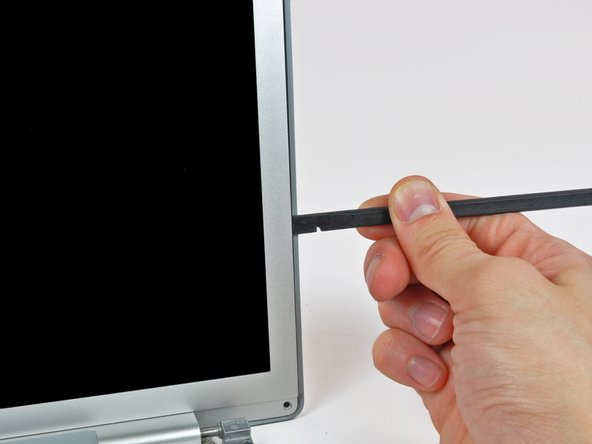
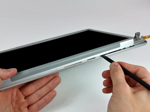
Insert the flat end of a spudger perpendicular to the face of the display between the plastic strip attached to the rear bezel and the front bezel.
-
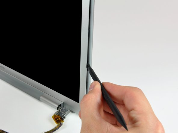
With the spudger still inserted, rotate it away from the display to separate the front and rear bezels.
-
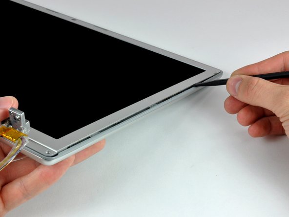
Work along the right edge of the display until the rear bezel is evenly separated from the front bezel.
-
-
Dieser Schritt ist noch nicht übersetzt. Hilf mit, ihn zu übersetzen!
-
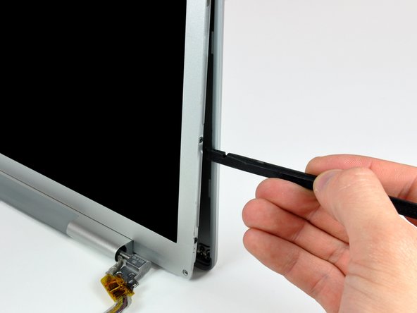
Insert your spudger between the front and rear display bezels at the lower right corner of the display.
-
Pry the rear bezel away from the front bezel to slightly separate the bottom edge of the rear display bezel.
-
-
Dieser Schritt ist noch nicht übersetzt. Hilf mit, ihn zu übersetzen!
-
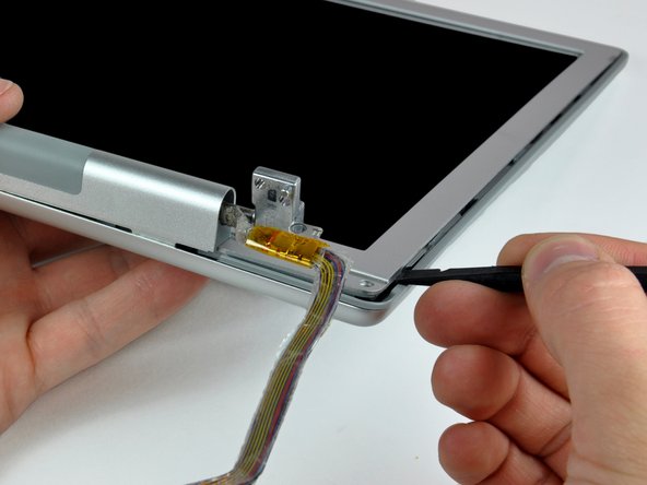
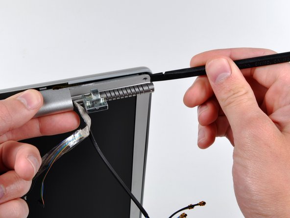
Insert the flat end of a spudger into the gap between the rear display bezel and the clutch cover.
-
Twist the spudger to separate the lower edge of the rear display bezel from the clutch cover.
-
Work along the lower edge of the rear bezel until it is evenly separated from the clutch cover.
-
-
Dieser Schritt ist noch nicht übersetzt. Hilf mit, ihn zu übersetzen!
-
Now that the right and bottom edges of the rear bezel are slightly separated from the front bezel, use a spudger to pop the rear bezel off the tabs near the lower right corner of the display.
-
-
Dieser Schritt ist noch nicht übersetzt. Hilf mit, ihn zu übersetzen!
-
Insert the flat end of a spudger between the front bezel and the plastic strip attached to the rear bezel near the screw holes at the bottom corners of the display.
-
Rotate your spudger toward the rear bezel to separate it from the front bezel.
-
-
Dieser Schritt ist noch nicht übersetzt. Hilf mit, ihn zu übersetzen!
-
Slightly lift the lower edge of the display and pull it away from the rear display bezel.
-
The rear display bezel remains.
-
-
Dieser Schritt ist noch nicht übersetzt. Hilf mit, ihn zu übersetzen!
-
Remove the piece of tape securing the backlight cables to the front display bezel.
-
-
Dieser Schritt ist noch nicht übersetzt. Hilf mit, ihn zu übersetzen!
-
Carefully lift the inverter out of the clutch cover.
-
-
Dieser Schritt ist noch nicht übersetzt. Hilf mit, ihn zu übersetzen!
-
Disconnect the inverter cable by pulling its connector away from the socket on the inverter board.
-
-
Dieser Schritt ist noch nicht übersetzt. Hilf mit, ihn zu übersetzen!
-
Disconnect the backlight connector from the inverter board.
-
Remove the inverter from the display.
-
-
Dieser Schritt ist noch nicht übersetzt. Hilf mit, ihn zu übersetzen!
-
Use the flat end of a spudger to carefully peel off the three antenna straps stuck to the lower edge of the LCD.
-
-
Dieser Schritt ist noch nicht übersetzt. Hilf mit, ihn zu übersetzen!
-
Remove the five Phillips screws securing the clutch cover to the bottom edge of the front display bezel.
-
-
Dieser Schritt ist noch nicht übersetzt. Hilf mit, ihn zu übersetzen!
-
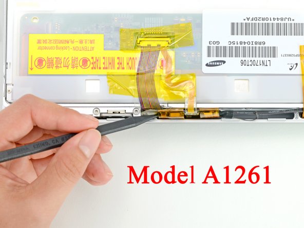
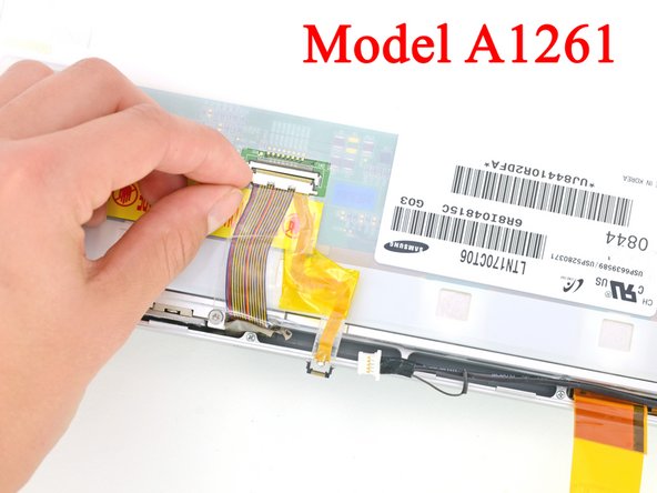
Remove the two pieces of tape securing the display data cable to the LCD.
-
-
Dieser Schritt ist noch nicht übersetzt. Hilf mit, ihn zu übersetzen!
-
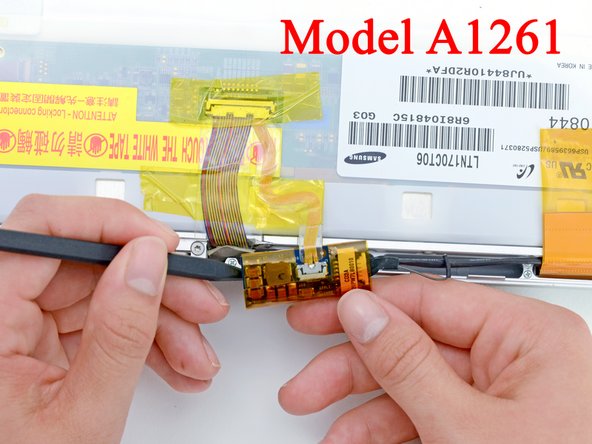
Disconnect the display data cable from the LCD by pulling it toward the bottom edge of the display.
-
-
Dieser Schritt ist noch nicht übersetzt. Hilf mit, ihn zu übersetzen!
-
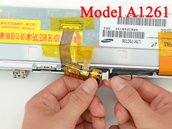
Move the display data cable out of the way to remove the Phillips screw hidden underneath.
-
-
Dieser Schritt ist noch nicht übersetzt. Hilf mit, ihn zu übersetzen!
-
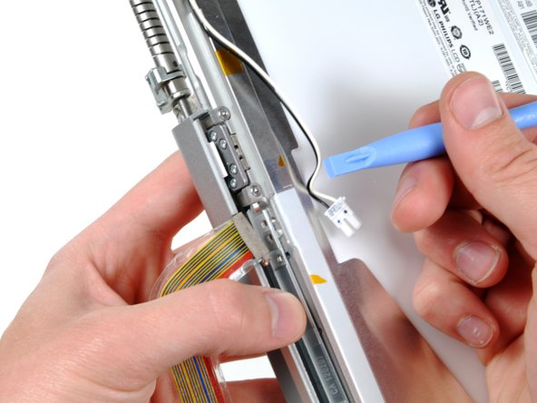
While pulling the clutch assembly away from the clutch hinge with one hand, insert an iPod opening tool between the clutch cover and the front display bezel to lift the clutch cover over the retaining pin on the front display bezel.
-
Pull the clutch assembly away from the front display bezel.
-
-
Dieser Schritt ist noch nicht übersetzt. Hilf mit, ihn zu übersetzen!
-
Repeat the process covered in the previous step to free the other side of the clutch assembly from the front display bezel.
-
-
Dieser Schritt ist noch nicht übersetzt. Hilf mit, ihn zu übersetzen!
-
Remove the clutch assembly from the front display bezel, minding any cables that may get caught.
-
-
Dieser Schritt ist noch nicht übersetzt. Hilf mit, ihn zu übersetzen!
-
Remove the display data cable from the display assembly.
-
-
Dieser Schritt ist noch nicht übersetzt. Hilf mit, ihn zu übersetzen!
-
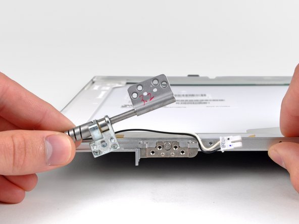
Remove the four 3.5 mm T6 Torx screws securing the right clutch hinge to the front display bezel.
-
Remove the right clutch hinge from the front display bezel.
-


Rückgängig: Ich habe diese Anleitung nicht absolviert.
5 weitere Nutzer:innen haben diese Anleitung absolviert.
