Einleitung
Benutze diese Anleitung, um ein defektes Logic Board zu ersetzen. Biite beachten: Vor dem Anbringen des Kühlkörpers ist unbedingt eine neue Schicht Wärmeleitpaste aufzubringen.
Was du brauchst
-
-
Entferne die folgenden 10 Schrauben, die das Gehäuseunterteil mit dem Deckel verbinden:
-
Drei 13.5 mm Kreuzschlitzschrauben
-
Sieben 3 mm Kreuzschlitzschrauben
-
-
-
Zwänge deine Finger zwischen das Gehäuseunterteil und die Lüftungsschlitze und ziehe das Unterteil nach oben, um die Clips zu lösen, mit denen das Gehäuseunterteil am Deckel befestigt ist.
-
Entferne das Gehäuseunterteil.
-
-
-
Falls vorhanden, ziehe die kleine Plastiklasche am Akkustecker gegen die Vorderkante des Geräts. Bei Modellen von Ende 2011 hat der Stecker keine Lasche und ist einfach direkt im Motherboard eingesteckt. In diesem Fall ziehe den Stecker gerade nach oben, um ihn zu entfernen.
This step is a little difficult in reverse, that is, when re-attaching the battery. It helps to tilt the laptop up so you can see the edge of the board that accepts the plug. It may look like there are two slots for it, it goes in the bigger slot that is further away from the board.
Is this step really necessary? It is not part of the instructions how to replace the HDD in Apple's User Manual of the 2011 17" MBP.
As it says in the step: "Whenever working near the logic board, it is always wise to first disconnect the battery to avoid short circuits." It is not required, but it is simple insurance to avoid a $1000+ repair should you accidentally short components on the board with something metal.
There was no tab on my model. Battery is affixed to board and screws must be removed.
Mine also, and looks as if removing connector could damage motherboard.
Stephen -
The battery on my 17” mid-2010 (MC024LL/A -A1297 ) is held by 3 specialty screws CR-V1 (3-wings similar to Mercedes-Benz tri-star)
It has a tab which I pulled straight up
The connector to the motherboard came away easily by pulling toward the front edge.
* There is no tab on the A1297 (late 2011) model's battery connector. Be careful with the connector, it chips off the edges easily! Otherwise the same as bhodges2 & Stephen's notes.
** (Pleas also include the exact Model and Part numbers like P/N: MD311D/A; Mod.: A1297 in the comments and notes for your MBP)
Why are there no guides for the Late 2011 17" MacBook Pro A1297 (2.4GHz i7 quad core, MD311LL/A)??? I just replaced the RAM in mine and discovered that not only is there no tab on the battery connector, but the connector pulls straight up, perpendicular to the logic board, rather than parallel. I almost ripped the wires out of the connector by trying to pull it out parallel to the logic board like this guide instructed! After finally getting it out, my advice to those with the Late 2011 model is to use a spudger to loosen the edges of the connector then lift the connector straight up to get it out safely.
I replaced the display on my late 2011 model and noticed that it was quite different than the tutorial given here so I detailed all the differences to help others with late-2011 models on my blog: http://johnfixesstuff.blogspot.com/2014/...
jmueller -
With some dexterity and carefulness, the MagSafe could be removed from its place without the need to remove the whole logic board!
Same here, I used a head-band light to see it and got it done without removing anything but the battery connection, the charging port and the display data cable. Then I had to do it again because amazone sent me the wrong charging port, the board has different width between screw holes, and on closer look, different components soldered on, also. AND, one is labeled 2008, the other 2009… make sure you get the correct one, the other ( “wrong”? ) might work, but I’m not risking it! So why does the 2008 fit in my 17” macbook pro(5,2) mid-2009 and the one labeled 2009 does not fit ? It is what it is…
The battery on my 17” mid-2010 (MC024LL/A -A1297 ) is held by 3 specialty screws CR-V1 (3-wings similar to Mercedes-Benz tri-star)
It has a tab which I pulled straight up
The connector to the motherboard came away easily by pulling toward the front edge.
-
-
-
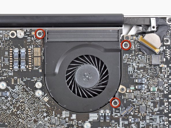
Hebe den Stecker des rechten Lüfters mit dem flachen Ende eines Spudgers aus seinem Anschluss auf dem Logic Board heraus.
Needs a better photo to show how the plug is able to come off the socket vertically. In particular, the underside of the plug should be shown.
-
-
-
Entferne die drei 3,1 mm Kreuzschlitzschrauben, mit denen der rechte Lüfter am Logic Board befestigt ist.
The fan fixing screws on my 17-inch, Mid 2010 MacBook Pro were Torx 6, not Philips 00.
... And the fan fixing screws on my 2009 MBP were *smaller* that the size implied by the tool requirements for this project. I initially tried a Phillips 00 screwdriver but it nearly stripped the screw head. It was necessary to switch to a Phillips 000 bit to actually get two of the screws to move.
RichardL -
my mid 2010 mbp had Torx 7
Mine stripped and now I can't get it out, Phillips #00 is too large
Not a big deal maybe but I have an Early 2011 and it doesn’t have the plastic tab on the battery connector (as if it were a Late 2011) AND it uses torx screws. So if you’re planning to tear into a 2011, get a torx screwdriver—there’s a chance you might need it even if you don’t have a Late 2011
-
-
-
Entferne den rechten Lüfter vom oberen Gehäuse, achte dabei darauf, dass sich keine Kabel verfangen.
-
-
-
Hebe den Stecker des linken Lüfters mit dem Spudger aus seinem Anschluss auf dem Logic Board heraus.
-
-
-
Entferne die drei 3,1 mm Kreuzschlitzschrauben, mit denen der linke Lüfter am Logic Board befestigt ist.
-
Entferne den linken Lüfter vom oberen Gehäuse, achte dabei darauf, dass sich keine Kabel verfangen.
-
-
-
Klappe den Sicherungsbügel am Flachbandkabel der Tastaturbeleuchtung mit dem Spudger oder dem Fingernagel hoch.
-
Ziehe das Flachbandkabel der Tastaturbeleuchtung aus seinem Anschluss heraus.
On my early 2011 Macbook Pro unibody 17” - there is another small cable to disconnect between this, the keyboard backlight ribbon cable and the optical drive cable. Not sure what it’s for, but thought to mention is. It is small metal plug and socket and says “AC” on it.
-
-
-
Drücke die kleine Kunstoffkabelhalterung mit der Spudgerspitze vom Anschluss des Kamerakabels weg, so dass genug Platz zum Ausbau des Kamerakabels entsteht.
Bit of a levering horizontally. Remove the carbon fibre patterned tape off the top of the connector to expose the connector then slide (break the adhesive bond) on the small oblong black plastic passed, towards the optical drive module. The connector can then be disengaged. It's quite difficult to unlatch the connector! Take extreme care
not on my 17” late 2011
On my late 2011 MBP there are two connectors at this place: One big connector like the silver one shown on the fotos (but in my case it is black), and the tiny one as discribed in the comment from anon 10/14/2017). In contrast to the fotos, this tiny connector is on the opposite side of the big one, on the edge close to the right fan. To disconnect this connector, follow the instructions from anon 10/14/2017.
The cable going to the big connector is in my case a wide black ribbon cable running diagonically over the optical drive. To remove the connector of this cable from the socket, pry it upwards carefully with your fingernails or a spudger.
-
-
-
-
Ziehe das Kamerakabel zur Öffnung des optischen Laufwerks hin und trenne es vom Logic Board ab.
This step and the previous one (plastic retainer) were very different on my logic board. It's an early 2011, 17" that I bought second hand. I'm wondering if the logic board was previously replaced.
-
-
-
Heble den Stecker des optischen Laufwerks mit dem flachen Ende des Spudgers aus seinem Anschluss auf dem Logic Board hoch.
-
-
-
Heble den Stecker des Tieftöners und des rechten Lautsprechers mit dem flachen Ende des Spudgers aus seinem Anschluss auf dem Logic Board hoch.
-
-
-
Klappe mit dem Fingernagel oder der Spudgerspitze den Sicherungsbügel am Anschluss des Infrarotsensor-Flachbandkabels hoch.
-
Ziehe das Infrarotsensor-Flachbandkabel aus seinem Anschluss heraus.
The IR sensor cable also connects the Hall Effect switch that detects whether the lid is closed or open (and thus shuts off the display, puts the computer to sleep, wakes it up, etc.) to the logic board.
How do I know? I re-pasted my late 2011 17" MBP and forgot to reconnect it. The machine would not sleep automatically when the lid was closed anymore. Re-connecting the cable fixed it.
thanks for the info !!!! i got the same problem with sleep because the cable was not properly connected
-
-
-
Entferne folgende vier Schrauben:
-
Zwei 3,5 mm Kreuzschlitzchrauben
-
Zwei 1,6 mm Kreuzschlitzschrauben
-
Entferne die beiden Steckerabschirmungen vom Logic Board.
On my early 2011 laptop, the screws on the left hand shield were T6 screws. The others were Phillips head.
The same applies to the late 2011 model.
on my early 2011 model it seems that on the left hand shield (with the Torx screws) the track pad connector is stuck to the underside of the connector. It lifted off the logic board when I tried to remove the shield and I am leaving it like that until I can manage to access it better - maybe when the logic board is out.
-
-
-
Heble den Trackpadstecker mit dem flachen Ende des Spudgers aus seinem Anschluss auf dem Logic Board hoch.
-
-
-
Klappe mit dem Fingernagel den Sicherungsbügel am Anschluss des Tastatur-Flachbandkabels hoch.
-
Ziehe das Tastatur-Flachbandkabel aus seinem Anschluss heraus.
Thanks for the great guide!
Tip for re-seating the keyboard cable: put a piece of sticky tape on, fold over at the top end, re-seat the connector (carefully!) with a spudger and (gently!) pull the tape 'over' the connector on the logic board until you feel it nudges in fully. Notice the emphasis on "carefully" and "gently"... :)
Thanks for this manual! I used it to replace the keyboard. I would not recommend it as an easy job and it is not described on Ifixit for unknown reasons. But I did it and everytinhg worked fine. 2 remarks about the conncetion for the keyboard. In my Macbook 17 Pro (mid 2009) there is a litlle lever that clamps the keyboard 'cable'. You can get it out easily (I did that too because I did not see it then), but to reassemble it it is better to uplift the little lever and then move the 'cable' in with sticky tape (thanks for that tip!)
I had to redo it 3 times to get it working. With the lever up and then clamping the 'cable' by pushing it down it worked AND it solved the power button problem. Please be carefull as said in the manual, it is all very delicate!
And for replacing the keyboard; prepare yourself for a lot of tiny screws! (some of them are stuck and had to be removed with force, be warned!)
Another tip
-
-
-
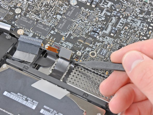
Klappe mit dem Fingernagel den Sicherungsbügel am Anschluss des Flachbandkabels des Expresskartengehäuses hoch.
-
Ziehe das Flachbandkabel des Expresskartengehäuses aus seinem Anschluss heraus.
It might be easier to remove the ExpressCard ribbon cable in Step 18 by removing the Hard Drive cable first...use your judgment.
-
-
-
Hebe den Festplattenkabelstecker mit dem flachen Ende des Spudgers aus seinem Anschluss auf dem Logic Board hoch.
-
-
-
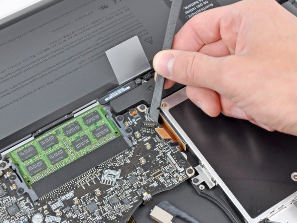
Klappe mit dem Fingernagel den Sicherungsbügel am Anschluss des Akkuladeanzeige-Flachbandkabels hoch.
-
Ziehe das Akkuladeanzeige-Flachbandkabel aus seinem Anschluss heraus.
When reassembling, slide the ribbon cable underneath the connector then lock it into place.
-
-
-
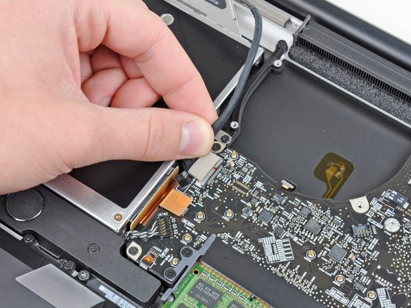
Hebe die Kunstoffklappe am Halter des Displaydatenkabels an und drehe sie zur Seite mit der Ladebuchse hin.
-
Ziehe das Displaydatenkabel aus seinem Anschluss heraus.
Be SUPER EXTRA CAREFUL when connecting this cable back!!! Use a magnifying glass or headset to see what you are doing.
When I plugged it in the first time (finished the rest of the process and restarted the mac) I got green lines all over my screen…
I replugged it a total of 4 times to get it right even cleaned it with alcohol. Now everything is working, but I freaked out a bit :)
I would describe the removal as “sliding back towards the corner". “Pulling out", to me, implies pulling up away from the board.
When reassembling, slide the cable underneath the connector. It doesn’t snap on.
This is the trickiest step in this whole process, both detaching and reattaching. I’ve been through this logic board repair scenario with my Early 2011 about 4x now, and if, when you reassemble, you’re still having problems with your display of any sort, this is your number 1 achilles heel is this connector getting dirty (use high purity over 90% isopropyl alcohol often found at drug stores next to the regular 70% stuff for cleaning) or not seating properly. I have broken off the connector bracket mount that goes over the top but was able to use pure silicone to safely reattach it. Don’t break that top bracket off sliding this puppy out; it’s a very dicey situation!
I had no idea what "toward the DC-in side" meant. "DC-in" refers to the Magsafe connector/port in the corner of the machine (upper right when the machine is facedown with lower case removed).
The plastic flap and its little metal bracket broke off from the cable when I tried to rotate it out of the socket. Will this cause problems? I'm assuming it was just a handle. I was successfully able to slide the cable out, and then back into the socket on reassembly, even after the bracket/tab broke off.
-
-
-
Entferne folgende acht Schrauben, mit denen das Logic Board und die Versorgungsplatine (DC-In Board) am oberen Gehäuse befestigt sind:
-
Sechs 3,2 mm Kreuzschlitzschrauben
-
Zwei 7,6 mm Kreuzschlitzschrauben
The Six 3.2mm screws can in some cases be torx instead of phillips
I've got a great idea for keeping the tiny screws safe and also labelled up e.g. these 6+2 screws belong to the logic board - simply use 'Post-It' sticky note upside down on your desk and use the sticky bit to keep the screws from rolling around getting themselves lost :-)
-
-
-
Hebe die Logic Board-Einheit an der Seite nahe am optischen Laufwerk an und hebe sie vom oberen Gehäuse weg.
-
Ziehe die Anschlüsse und die Versorgungsplatine (DC-In Board) von der Seite des oberen Gehäuses weg und entferne die Logic Board Einheit, achte dabei darauf, dass sich keine Kabel verfangen.
When lifting the logic board be careful! The rubber foam around the microphone may have adhered the microphone to the uppercases grill work so as you lift you could rip the connector from the ribbon cable.
* Take a small spatula and thought the fan opening carefully dislodge the microphone from the grill as you lift the logic board.
* To locate the microphone note on the next slide the small unit between the fingers of the hands.
Attach the DC connector with screws first when reassembling.
-
-
-
Entferne die acht 8,3 mm Kreuzschlitzschrauben, mit denen der Kühlkörper am Logic Board befestigt ist.
My heat sink did not look like this. It did not have the ninety degree bend to the left at the bottom. It was just "T" shaped, not like the "J" shape depicted here. Does this mean the logic board was previously replaced? (Early 2011, 17-inch, 2.2GHz)
No, I think that it is just different on the early 2011 model, mine is the same. There are lots of small and larger differences between this guide and our model. There are only 6 screws,
Lami -
-
-
-
Klemme das Kabel des Wärmesensors am Kühlkörper zwischen deinem Daumen und der Spudgerspitze ein.
-
Hebe den Spudger hoch und hebe dabei den Stecker am Kabel des Wärmesensors aus seinem Anschluss auf dem Logic Board heraus.
My mid-2009 MBP didn’t have a connector (socket is on the board, but there’s no cable to be plugged into it). Found in an Apple technician manual a mention that some versions of the MBP don’t have the thermal sensor, so apparently that’s okay.
-
-
-
Entferne den Kühlkörper vom Logic Board.
Bonjour. Peut-on remplacer la pâte thermique d’origine par des pads thermiques au graphite? Merci
-
-
-
Ziehe den Stecker der Versorgungsplatine (DC-In Board) aus seinem Anschluss auf dem Logic Board heraus.
-
-
-
Entferne die beiden 7,9 mm Kreuzschlitzschrauben, mit denen der linke Lautsprecher am Logic Board befestigt ist.
-
-
-
Hebe die linke Lautsprechereinheit etwas vom Logic Board weg.
-
Hebe die Stecker vom linken Lautsprecher und vom Mikrofon mit dem flachen Ende des Spudgers aus ihren Anschlüssen auf dem Logic Board heraus.
Mind the microphone doesn’t come out of its hole when you reassemble.
-
-
-
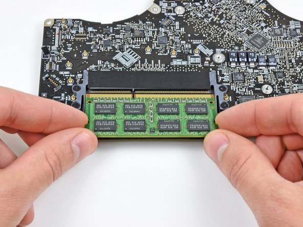
Drücke die Rasten auf jeder Seite des RAM-Riegels gleichzeitig nach außen, so dass sie sich lösen.
-
Wenn der Riegel aufgeklappt ist, kannst du ihn gerade aus dem Sockel herauszuziehen.
-
Das Logic Board bleibt übrig.
-


Befolge diese Anweisungen in umgekehrter Reihenfolge, um dein Gerät wieder zusammenzubauen.
Befolge diese Anweisungen in umgekehrter Reihenfolge, um dein Gerät wieder zusammenzubauen.
Rückgängig: Ich habe diese Anleitung nicht absolviert.
99 weitere Nutzer:innen haben diese Anleitung absolviert.
Besonderer Dank geht an diese Übersetzer:innen:
100%


Diese Übersetzer:innen helfen uns, die Welt zu reparieren! Wie kann ich mithelfen?
Hier starten ›

13 Kommentare
Good question! We’ve had good quality Ethernet cables easily slip out of the jacks on several of our MacBook Pros (and TiBook) over the years.
hi Andrew... My macbook pro retina.. When starting up, the progress bar gors slow, then macbook suddenly shuts down.. But before that, there is a grain/noise of rainbow colors across the hole screen showing up.. .. Do you regocnize the problem and what can it be, the graphic / logic card?
Thank you.
This seems to be the known gpu problem with AMD Radeon 6770 chip. They lose the soldering connection because of the heat the gpu produces, the solder nearly melts and when cooling down it gets hard again and this torture brings the solder to break at any point. There has been a big replacement program by apple this ended 31.12.206 I think. The only chance of reactivating is disabling the Radeon. There is a software hack for this. But it would be better to go further and do the hardware modification too, because with an nvram reset or some os update the software hack is away and you have to do all the steps again. Google for Tiresias GPUkiller, that seems to be a stable solution.
There is no easy way to remove any part of the Keyboard!!
The steps for the removal of the logic board represents the major steps before getting access to removing the keyboard on the 17 inch..There exists a full 13 inch MacBook Pro description on keyboard removal. I suggest once you have the 17 inch logic board out you could study the 13 inch description to figure out keyboard removal.
my logic board from 2009 (Core 2 Duo T9800) died . is it possible to put the i7 2011 2.5 GHz Core i7 (I7-2860QM) or the body and the connectors won't fit ?
important to reassemble the "lower case" successfully: the threads of the seven 3mm phillips screws are drilled at an angle :-/
mysterioes - Antwort
Same issue with me. After reassembling my 13-inch and my 17-inch, one of the screws are sticking out ever so slightly. Very annoying, especially since I scratch whatever surface I'm on now.
Kyle Spadaro -
Very important note; this guide is NOT correct for the Macbook Pro 17" A1297 late '11.
The A1297 has an assembly adjacent to the optical drive, identifiable by 4 antenna connectors, 1 usb cable (with very small connector) and one PCI-e flat cable running across the optical drive.
I did not take pictures, but found one on the web. I'm very new to iFixit and have no idea yet on how to create a guide, but here's the picture showing the assembly on top (this pic only has 3 antenna wires, the A1297 has 4, but at least you'll know what to look for.
- carefully undo all connections and 2 screws
- remove the assembly and flip it over
- again carefully remove the shielding tape
- undo 3 tiny screws
- gently pry the airport card from the assembly (the flat cable will be a bit of a pain)
- reverse process with replacement card.
image can be found here:
https://dl.dropboxusercontent.com/u/2446...
Remon - Antwort
It helps if you mark the holes where the long screws go so you can easily find them when the time comes to button things up. Also, a little dish or custard cup to hold those tiny screws is essential.
Human - Antwort
3 x 13.5 mm screws are actually TWO different types! Return to EXACT SAME HOLES.
-I discovered this on my mid-2010, but from comments, sounds like it may affect other models as well
2 x 13.5 mm screws are pointed ends
1 x 13.5 mm screw is a FLAT end <- CORNER HOLE
These areTWO slightly different lengths, and must return to correct holes. If you put the flat end screw in the wrong hole, it will stick out slightly. If you put either of the pointed screws in the wrong hole, they will go in all the way, but will not catch threads, and will simply fall out when laptop is flipped back over.
scottbernardis - Antwort
I printed out the image above and taped each screw to the photo as I removed each one, just to make sure I put them in the right location.
Grace Morris - Antwort
This is a brilliant suggestion! I did this for all the steps that involved removing screws, numbered the sheets, and that made it very easy to put it all back together in reverse. Thanks!
Steve Adamczyk -
Be sure to use Loctite on the screws when re-attaching the bottom of the computer. The screws can and will fall out once they have been removed for repairs if you do not put Loctite on them when you reuse them. Otherwise, purchase new screws before repairing the computer as the new screws come with Loctite material on them. (I have personal experience with this problem.)
johnpartridge - Antwort
Be sure NOT to Buy this Battery from iFixit. I bought it from eustore.ifixit.com and the Condition of Battery is : Service Battery ,
from the &&^&^$^ first day.
Till today my battery Cycle Count is: 80.
I’ve tried everything as: Battery Calibration, resetting the SMC, PRAM, reinstalling the battery,
and Service Battery warning still there.
Just DO NOT BUY crappy, trash from here.
I have very bad experience.
Doruntin Koci - Antwort
Hi Doruntin,
we’re more than sorry to hear about your bad experience.
I’ll inform our customer service team who’ll reach out to you and offer either a replacement or reimbursement.
If ever you’d need assistance again, please feel free to directly write to eustore@ifixit.com, as comments are not regularly checked for service issues.
I’m confident that we’ll find the solution that suits you best!
Sandra Hiller -
PLEASE OBSERVE: The image of the left speaker used is NOT for a 2011 model. A 17inch MacBook Pro A1297 - LEFT SPEAKER + MICROPHONE - 2011 has IDENTIFYING NUMBER: Apple Part #:922-9821, 922-9822. And its COMPATIBILITY: 17 inch MacBook Pro Unibody A1297 - Early 2011 MC725LL/A 2.2 i7 - Early 2011 MC725LL/A 2.3 i7 - Late 2011 MD311LL/A 2.4 i7 - Late 2011 MD311LL/A 2.5 i7
kenneth krabat - Antwort