Einleitung
The ins and outs of replacing your upper case.
Was du brauchst
-
-
With the case closed, place the Unibody top-side down on a flat surface.
-
Depress the grooved side of the access door release latch enough to grab the free end. Lift the release latch until it is vertical.
-
-
-
The access door should now be raised enough to lift it up and out of the Unibody.
-
-
-
Grab the white plastic tab and pull the battery up and out of the Unibody.
-
-
-
Remove the following eight screws securing the lower case to the chassis:
-
One 3 mm Phillips screw.
-
Three 13.5 mm Phillips screws.
-
Four 3.5 mm Phillips screws.
-
-
-
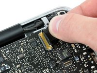
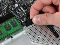
Disconnect the camera cable by pulling the male end straight away from its socket.
-
-
-
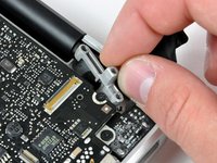
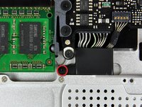
Remove the following screws securing the camera data cable and right speaker to the upper case:
-
One 9.9 mm partially threaded Phillips screw
-
One 9.6 mm threaded Phillips screw
-
One 4 mm Phillips screw
-
Slide the camera cable bracket out from under the subwoofer and remove it from the computer.
-
-
-
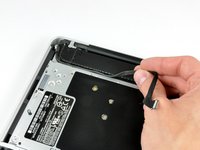
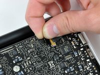
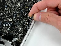
Grab the plastic pull tab secured to the display data cable lock and rotate it toward the DC-in side of the computer.
-
Pull the display data cable connector straight away from its socket.
-
-
-
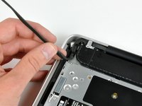
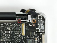
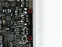
Remove the following two screws from the display data cable bracket:
-
One 7 mm Phillips screw.
-
One 5 mm Phillips screw.
-
Lift the display data cable bracket out of the upper case.
-
-
-
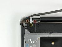
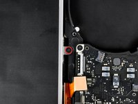
Remove the two outer 6 mm Torx screws securing each side of the display to the upper case (4 screws total).
-
-
-
Open your MacBook so the display is perpendicular to the upper case.
-
Place your opened MacBook on a table as pictured.
-
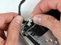
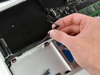
While holding the display and upper case together with your left hand, remove the 6 mm Torx screw from the lower display bracket.
-
-
-
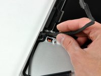
Remove the last remaining 6 mm Torx screw securing the display to the upper case.
-
-
-
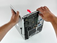
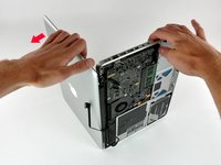
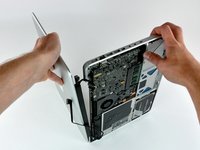
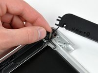
Grab the upper case with your right hand and rotate it slightly toward the top of the display so the upper display bracket clears the edge of the upper case.
-
Rotate the display slightly away from the upper case.
-
Lift the display away from the upper case, minding any brackets or cables that may get caught.
-
-
-
-
Remove the single Phillips screw securing the hard drive bracket to the chassis.
-
-
-
Lift the hard drive by its pull tab enough to grab and remove the retaining bracket.
-
Lift the hard drive out of the chassis, minding the cable attaching it to the computer.
-
-
-
Remove the hard drive from its cable by pulling the cable connector straight away from the drive.
-
-
-
Remove the four 10.3 mm Phillips screws securing the mid wall to the upper case.
-
-
-
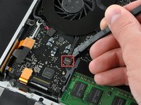
Remove the following three screws securing the fan to the upper case:
-
Two 5 mm Phillips screws.
-
One 7 mm Phillips screw.
-
-
-
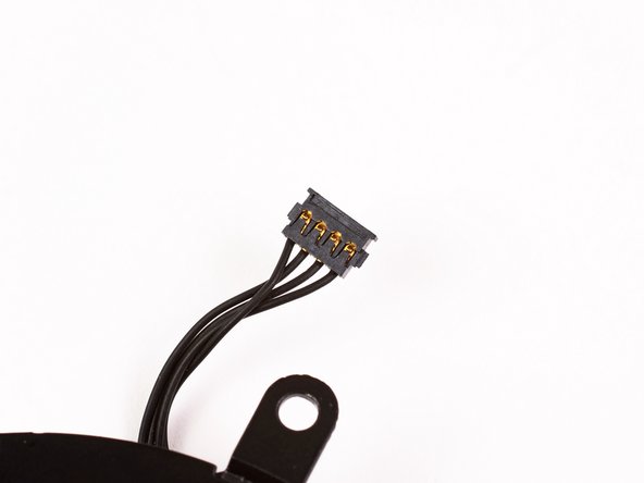
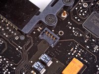
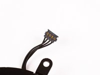
Use a spudger to pry the fan connector straight up and out of its socket on the logic board.
-
-
-
Using the flat end of a spudger, pry the subwoofer connector straight up off the logic board.
-
-
-
Use a spudger to pry the optical drive connector straight up off the logic board.
-
-
-
Use the flat end of a spudger to pry the hard drive cable connector straight up off the logic board.
-
-
-
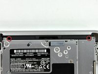
Remove the three 2.5 mm Phillips screws securing the optical drive to the upper case.
-
-
-
Peel the hard drive cable from the adhesive securing it to the upper case, and maneuver the plastic retaining block out of the upper case.
-
-
-
Peel back the small piece of black tape covering the right speaker cable.
-
Use the tip of a spudger to pry the right speaker up off the adhesive securing it to the upper case.
-
Lift the subwoofer and right speaker assembly out of the upper case.
-
-
-
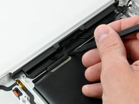
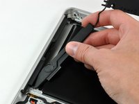
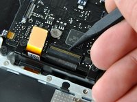
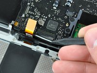
Use the tip of a spudger to flip up the locking lever to release the IR sensor ribbon cable from its socket.
-
Pull the IR sensor ribbon cable straight away from the logic board.
-
-
-
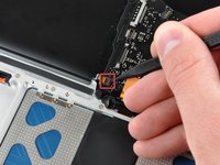
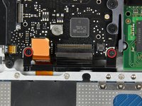
Use the flat end of a spudger to pry the trackpad connector straight up off the logic board.
-
-
-
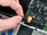
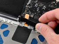
Using the tip of a spudger, flip up the keyboard ribbon cable retaining flap.
-
Pull the keyboard ribbon cable straight out of its socket.
-
-
-
Remove the two 5 mm Phillips screws securing the keyboard flex bracket to the upper case.
-
Lift the keyboard flex bracket out of the upper case.
-
-
-
Remove the single Phillips screw securing the battery cable cover to the upper case.
-
Remove the battery cable cover from the upper case.
-
-
-
Use a spudger to pry the battery level indicator cable connector straight up off the logic board.
-
-
In diesem Schritt verwendetes Werkzeug:Tweezers$4.99
-
Disconnect the battery cable connector by pulling it straight away from the logic board.
-
-
-
Remove the two 4mm Phillips screws securing the bottom case clip to the upper case.
-
Lift the bottom case clip out of the upper case.
-
-
-
Remove the following five screws securing the logic board to the upper case:
-
Four 3 mm Phillips screws.
-
One 3.5 mm Phillips screw.
-
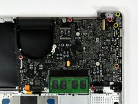
Remove the two 7 mm Phillips screws securing the DC-in board to the upper case.
-
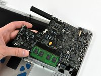
Lift the logic board from its left edge and pull it out of the upper case.
-
-
-
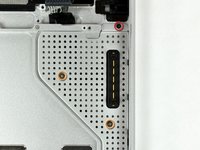
Remove the following screws securing the battery connector cover to the upper case:
-
One 2.5 mm Phillips screw.
-
Two 1.5 mm Phillips screws.
-
Lift the battery connector cover out of the upper case.
-
-
-
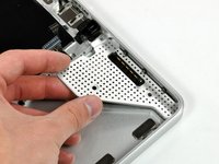
De-route the battery connector cable through the gap in the upper case and remove it from the computer.
-


To reassemble your device, follow these instructions in reverse order.
To reassemble your device, follow these instructions in reverse order.
Rückgängig: Ich habe diese Anleitung nicht absolviert.
26 weitere Personen haben diese Anleitung absolviert.

Ein Kommentar
Having difficulty putting that keyboard ribbon cable back in?
MacBook unibody keyboard ribbon cable won't go in
Put some scotch tape on it and pull up and in.