Diese Version enthält möglicherweise inkorrekte Änderungen. Wechsle zur letzten geprüften Version.
Was du brauchst
-
-
Löse die acht 4 mm Kreuzschlitz Schrauben, die die untere Abdeckung befestigen.
-
-
-
Hebe die untere Abdeckung vorsichtig in der Nähe der Lüftungsöffnung an.
-
Öffne den Spalt weiter mit den Fingern, bis sich die Abdeckung von den verbleibenden Clips löst.
-
-
-
Hebe den Akkuanschluss mit dem flachen Ende des Spudgers aus seinem Sockel auf dem Logic Board.
-
-
-
Entferne die folgenden Schrauben auf der Seite mit dem optischen Laufwerk am hinteren Lüftungsgitter:
-
Zwei 10 mm Torx T8 Schrauben
-
Zwei 5,2 mm Kreuzschlitzschrauben
-
-
-
Entferne folgende Schrauben von der Seite mit den Anschlüssen am hinteren Lüftungsgitter:
-
Zwei 10 mm Torx T8 Schrauben
-
Zwei 5,2 mm Kreuzschlitzschrauben
-
-
Dieser Schritt ist noch nicht übersetzt. Hilf mit, ihn zu übersetzen!
-
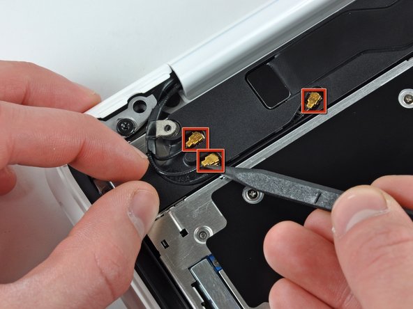
Remove the single 3 mm Phillips screw securing the AirPort/Bluetooth antenna ground strap to the rear speaker.
-
-
Dieser Schritt ist noch nicht übersetzt. Hilf mit, ihn zu übersetzen!
-
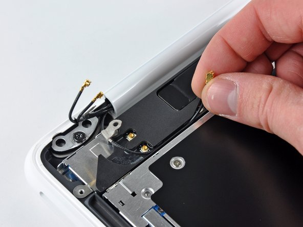
Use the tip of a spudger to pry the AirPort and Bluetooth antenna connectors (3 total) up off the AirPort/Bluetooth card.
-
De-route the long antenna from its channel in the rear speaker housing.
-
-
Dieser Schritt ist noch nicht übersetzt. Hilf mit, ihn zu übersetzen!
-
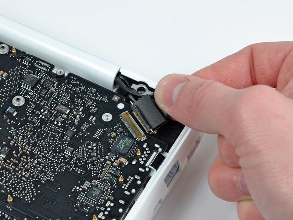
Grab the plastic pull tab secured to the display data cable lock and rotate it toward the DC-In side of the computer.
-
There is also a thin metal lock clip under the plastic tab that has to be released ( Use the tip of a spudger ) before you can disconnect the display data cable.
-
-
Dieser Schritt ist noch nicht übersetzt. Hilf mit, ihn zu übersetzen!
-
Gently pull the display data cable connector away from its socket on the logic board.
-
-
Dieser Schritt ist noch nicht übersetzt. Hilf mit, ihn zu übersetzen!
-
Open your MacBook so the display is perpendicular to the upper case.
-
Place your opened MacBook on a table as pictured.
-
While holding the display and upper case together with your left hand, remove the remaining 7.8 mm with lock washer T8 Torx screw from the lower display bracket.
-
-
Dieser Schritt ist noch nicht übersetzt. Hilf mit, ihn zu übersetzen!
-
Remove the last remaining T8 Torx screw securing the display to the upper case.
-
-
Dieser Schritt ist noch nicht übersetzt. Hilf mit, ihn zu übersetzen!
-
Grab the upper case with your right hand and rotate it slightly toward the top of the display so the upper display bracket clears the edge of the upper case.
-
Rotate the display slightly away from the upper case.
-
-
-
Dieser Schritt ist noch nicht übersetzt. Hilf mit, ihn zu übersetzen!
-
Lift the display up and away from the upper case, minding any brackets or cables that may get caught.
-
-
Dieser Schritt ist noch nicht übersetzt. Hilf mit, ihn zu übersetzen!
-
Insert the flat end of a spudger between the thin rubber strip surrounding the front display bezel and the rear display bezel.
-
Use the flat end of your spudger to carefully pry the front display bezel away from the adhesive securing it to the rear display bezel.
-
Continue prying until the front display bezel is free along the right side of the display and behind the right clutch hinge.
-
-
Dieser Schritt ist noch nicht übersetzt. Hilf mit, ihn zu übersetzen!
-
Use the flat end of a spudger to pry the front display bezel off the top edge of the display assembly.
-
Continue separating until the top edge of the front display bezel is free from the display assembly.
-
-
Dieser Schritt ist noch nicht übersetzt. Hilf mit, ihn zu übersetzen!
-
Use your spudger to pry the left side of the front display bezel away from the display assembly.
-
Carefully pry up the area behind the left clutch hinge.
-
-
Dieser Schritt ist noch nicht übersetzt. Hilf mit, ihn zu übersetzen!
-
Slowly work your way across the lower edge of the front display bezel until it is free from the display assembly.
-
When you get about half way across, pry up from the other side of the front display bezel's lower edge to ease the process.
-
-
Dieser Schritt ist noch nicht übersetzt. Hilf mit, ihn zu übersetzen!
-
Remove the front display bezel from the display assembly.
-
-
Dieser Schritt ist noch nicht übersetzt. Hilf mit, ihn zu übersetzen!
-
Remove the two 3 mm Phillips screws securing the clutch cover to the rear display bezel.
-
-
Dieser Schritt ist noch nicht übersetzt. Hilf mit, ihn zu übersetzen!
-
Insert the flat end of a spudger into the open end of the clutch cover and pry up to release it from the rear display bezel.
-
-
Dieser Schritt ist noch nicht übersetzt. Hilf mit, ihn zu übersetzen!
-
Remove the clutch cover from the display assembly.
-
-
Dieser Schritt ist noch nicht übersetzt. Hilf mit, ihn zu übersetzen!
-
Remove following six screws securing the LCD to the rear display bezel:
-
Four 3.4 mm Phillips.
-
Two 3 mm Phillips.
-
-
Dieser Schritt ist noch nicht übersetzt. Hilf mit, ihn zu übersetzen!
-
Hold the display vertically and tip it enough to grab the top edge of the LCD and rotate it slightly out of the display assembly, being careful not to break the circuitry off its lower edge.
-
-
Dieser Schritt ist noch nicht übersetzt. Hilf mit, ihn zu übersetzen!
-
Peel the piece of tape covering the display data cable connector away from the edge closest to the LCD.
-
-
Dieser Schritt ist noch nicht übersetzt. Hilf mit, ihn zu übersetzen!
-
Use the tip of a spudger to flip up the thin steel retaining clip securing the display data cable to its socket on the LCD.
-
Pull the display data cable straight away from its socket on the LCD.
-
Lift the LCD out of the display assembly and set it aside.
-
-
Dieser Schritt ist noch nicht übersetzt. Hilf mit, ihn zu übersetzen!
-
Remove the two small pieces of black tape securing the display data/camera cable to the rear display bezel.
-
-
Dieser Schritt ist noch nicht übersetzt. Hilf mit, ihn zu übersetzen!
-
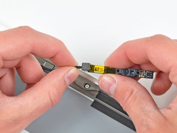
Use the pointed tip of a spudger to pry the camera board off the display assembly.
-
Disconnect the camera cable by pulling its connector away from the socket on the camera board.
-
-
Dieser Schritt ist noch nicht übersetzt. Hilf mit, ihn zu übersetzen!
-
De-route the display data/camera cable from the slot cut into the rear display bezel.
-
-
Dieser Schritt ist noch nicht übersetzt. Hilf mit, ihn zu übersetzen!
-
Carefully pull the display data/camera cable out from under the frame attached to the rear display bezel and remove it from the display assembly.
-
-
Dieser Schritt ist noch nicht übersetzt. Hilf mit, ihn zu übersetzen!
-
Remove the two small pieces of black tape securing the antenna cables to the rear display bezel.
-
-
Dieser Schritt ist noch nicht übersetzt. Hilf mit, ihn zu übersetzen!
-
Remove the four 2.3 mm Phillips screws securing the antennas to the rear display bezel.
-
-
Dieser Schritt ist noch nicht übersetzt. Hilf mit, ihn zu übersetzen!
-
Remove the single 3.3 mmm Phillips screw securing the lower antenna ground to the rear display bezel.
-
-
Dieser Schritt ist noch nicht übersetzt. Hilf mit, ihn zu übersetzen!
-
De-route the antenna cables from the groove cut into the rear display bezel.
-
Carefully pull the antenna cables out from under the frame attached to the rear display bezel and remove them from the display assembly.
-
-
Dieser Schritt ist noch nicht übersetzt. Hilf mit, ihn zu übersetzen!
-
Remove the three Phillips screws securing the center antenna to the rear display bezel.
-
-
Dieser Schritt ist noch nicht übersetzt. Hilf mit, ihn zu übersetzen!
-
Remove the center antenna from the rear display bezel.
-
-
Dieser Schritt ist noch nicht übersetzt. Hilf mit, ihn zu übersetzen!
-
Remove the three 4.7 mm T6 Torx screws securing the right clutch hinge to the rear display bezel.
-
Remove the right clutch hinge.
-
-
Dieser Schritt ist noch nicht übersetzt. Hilf mit, ihn zu übersetzen!
-
Remove the three 4.7 mm T6 Torx screws securing the left clutch hinge to the rear display bezel.
-
Remove the left clutch hinge.
-
Rear display bezel remains.
-


Rückgängig: Ich habe diese Anleitung nicht absolviert.
10 weitere Nutzer:innen haben diese Anleitung absolviert.

2 Kommentare
Guide is 100% accurate! My friend's macbook lid was cracked and scratched...looked awful. Bought a new one for about $30 and replaced it in under 1 hour for free. Didn't have a spudger, and as I'm sure you all know, you can't buy one at any store that I've found. So, I used a plastic putty knife from lowe's that I got for $0.98, and it worked great! The one thing I have to add is as follows: If your computer is rather old, have some additional adhesive to place on the front LCD bezel. The adhesive does not reapply very well. Double sided 3M tape will work great, but it will be a bit more difficult to remove a second time. Thanks iFixIt! Couldn't have done this without your help.
Anyone know what epoxy is used to secure the metal frame to the plastic cover? It's a green epoxy, but that's all I know. The same green epoxy is also used to secure the top case plastic to the metal frame