Einleitung
Das Logic Board enthält alle Anschlüsse auf der linken Seite.
Was du brauchst
-
-
Lege die Oberseite des Gehäuses mit geschlossener Klappe auf eine glatte Oberfläche.
-
Drücke den Verschlusshebel auf der geriffelten Seite der Klappe in das Gehäuse des MacBooks, bis du den Verschlusshebel auf der anderen Seite greifen kannst.
-
Öffne den Verschlusshebel so weit, dass er senkrecht steht.
-
-
-
Die Bodenklappe sollte nun ein kleines Stück offen stehen.
-
Die Klappe kann nun nach oben aus dem Gehäuse des MacBooks genommen werden.
-
-
-
Ziehe an der weißen Plastiklasche und damit den Akku gerade nach oben und aus dem Laptop.
Great tutorial ! great step !
-
-
-
Entferne die im Bild gezeigten acht Schrauben, die die Bodenplatte mit dem Rest des Gehäuses verbinden:
-
Eine 3 mm Kreuzschlitzschraube.
-
Drei 13,5 mm Kreuzschlitzschrauben.
-
Vier 3,5 mm Kreuzschlitzschrauben.
Make sure you have a good quality Phillips screwdriver. Mine had removable tips and had a small play at the connection. As a result I didn't have a good feel and damaged my screws (those securing the fan and the top left in step 23). Game over for me installing new thermal paste...
Be very carefull with your screws! Especially those on the inside.
You can get away with a Phillips #00 for many of the screws involved but the 4 at the bottom case split are likely to strip if you don’t use a JIS #00 or, in a pinch, a Phillips #000.
I used the Phillips #00 tip from my Pro Tech Toolkit, and it worked well enough. But yes, maybe #000 might have been better on the lower row of screws. Note to myself: Always read the comments first.
When replacing these screws, the order to replace them in is as follows:
1, Top left
2. Top right
3. Top center-left
4. Top center-right
5. Bottom center-right
6. Bottom center-left
7. Bottom right
8. Bottom left
I hope this information is helpful.
I followed my usual process of putting in all the screws loosely, then tightening them gradually in distributed pattern, to help ensure that the panel settles in place evenly. But maybe some orders are better.
-
-
-
Hebe die Bodenplatte mit beiden Händen an und entferne sie vom oberen Gehäuse.
Thanks for the guide!
It's implicit in the two photos, but worth mentioning because it blocked my progress in this step for a bit: You have to put the release latch back into its horizontal, closed position before you can lift off the lower-case panel.
-
-
-
Entferne die vier 10,3 mm Kreuzschlitzschrauben, die die Trennwand im Gerät befestigen.
-
-
-
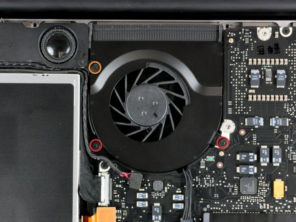
Benutze einen Spudger, um den Anschluss des Lüfterkabels vom Logic Board zu trennen.
Is there anyway to solder the fan socket back on to the mother board? It broke off :(
Solder back to the mother board!
Me too!!! WHAT NOW?
solder back to the mother board
It helped me a lot to look at the closeup pictures of the fan connector socket on the motherboard and the fan connector itself. Then I could figure out where to apply the axial rotating pressure with the plastic "spudger" (a trimmed old credit card). Needed more force to remove the 7-year old connection than I felt comfortable with. The pic's helped with the leverage point to use - just past and under the fan wires BUT not on the board itself.
Excellent guide! Moved fan from MB to MBP and installed new fan in old MB.
-
-
-
Entferne die folgenden drei Schrauben, die den Lüfter mit dem oberen Gehäuse verbinden:
-
Zwei 5 mm Kreuzschlitzschrauben.
-
Eine 7 mm Kreuzschlitzschraube.
Screws were locktited and I have stripped head of right one while trying to remove it…
same issue as Oleg. have tried multiple screwdrivers and they won’t budge.
-
-
-
Nimm den Lüfter aus dem Gehäuse.
One of the screw was messed up. How can I remove it ?
I ended up removing the three screws holding down the black gasket that the fan is attached to on the left hand side in the photo. Remove the two screws holding the speaker assembly. then you can remove the 3 screws running vertically down. One is on top of the dvd drive holding it down to the black chassis. dvd drive comes out as well, i followed the specific guide to get that out. Doing this let me flip the mobo out along with the fan, luckily the heatfin is separate from the fan.
Two of my screws did not want to come out when I used Philips #00 and it damaged the screw so now I don't know if I will manage to get it out. What can I do?
Don't know about ruined screw head removal, but for future reference: Place the tool lightly on screw head & rotate axially 'til the tool drops into the screw head for a comfortable, firm fit, before applying pressure & torque for screw removal. If the tool does not drop in the screw head for the comfortable, snug fit, you may have the wrong tool or the wrong size. Try a different size 'til U get the right fit before applying pressure & torque to remove the screw. It can save you grief from a ruined screw head.
-
-
-
Jeder der Anschlüsse ist anders, deshalb wird hier Schritt für Schritt gezeigt, wie man jeden einzelnen Anschluss trennt.
-
-
-
Entferne die eine Kreuzschlitzschraube, die die Abdeckung des Akkukabels mit dem oberen Gehäuse verbindet.
-
Entferne die Abdeckung des Akkukabels vom oberen Gehäuse.
-
-
-
-
Verwende einen Spatel, um das Kabel für die Akku-Anzeige gerade nach oben vom Logic Board zu hebeln.
-
-
-
Trenne den Akku-Kabelanschluss, indem du ihn gerade vom Logic Board wegziehst.
-
-
-
Benutze die Spitze Seite eines Spatels, um die Lasche, die das Tastatur Flachbandkabel befestigt, nach oben zu klappen.
-
Ziehe das Flachbandkabel gerade aus dem Anschluss heraus.
-
Wenn der kleine Anschluss rechts neben dem Tastatur Flachbandkabel besetzt ist, entferne dieses Kabel auf die gleiche Weise.
Trying to get this back in can be really difficult. But it works, just try and try again very patiently. After putting down the retaining flap again, pull a little bit to make sure the ribbon cable is all the way in and fixed.
My late 2008 Macbook 5,1 2.4GHz also had the tiny ribbon plug besides the keyboard ribbon plug polpulated as well (keyboard backlight?) - I missed it blindly following the guide but it made its presence clear when I lifted up the PCB - lucky I was not moving hastily severing the tiny ribbon!
So I added a comment at step 15 as in the guide this tiny plug is clearly not populated in contrast to my Macbook.
Kudos to the author - this guide clearly helped me a lot saving me a lot of time and head scratching.
By the way, minimal thermal paste was found on both CPU and GPU (the original reason I dissasembled my old Macbook) and after I put enough of this thermal transfering stuff on them the Macbook started working much-much cooler after years of hot operation that I thought were due to heavier OSX versions - should have done it 4-5 years ago!
What temp was your Macbook's CPU running at? I have cleaned out exhaust radiator thing, would it be worth redoing my thermal paste as well?
Jake -
@beefmangta With a machine of that age assuming the thermal paste has never been replaced, it is absolutely worth replacing. Certain aftermarket pastes such as Arctic MX-4 (which is available on Amazon) also tend to perform better than stock pastes in many cases.
I accidently cut the tiny cable labeled 21 on the right hand side of the cable highlighted in the photo. It’s for the keyboard backlight. It’s gone obviously but the comp still works without it connected
-
-
-
Benutze die Flache Seite eines Spudgers, um den Trackpad-Anschluss nach oben vom Logic Board abzuhebeln.
-
-
-
Hebe den Verschluss des IR-Sensor Flachbandkabels mit der Spitze eines Spudgers nach oben aus seiner Buchse heraus.
-
Ziehe das IR-Sensor Flachbandkabel mit der Spitze eines Spudgers aus dem Logic Board.
-
-
-
Benutze das flache ende eines Spudgers, um den Anschluss für das Festplattenkabel nach oben vom Logic Board abzuhebeln.
-
-
-
Benutze das flache Ende eines Spudgers, um das Kabel für das optische Laufwerk nach oben vom Logic Board abzuhebeln.
-
-
-
Trenne das Display-Datenkabel, indem du den Stecker gerade aus seiner Buchse ziehst.
-
-
-
Verwende das flache Ende eines Spudgers, um das Subwoofer Kabel vom Logic Board nach oben zu hebeln.
This will easily break, resulting in snapped pins. Will cause right speaker to not function if you don't solder them back on. I don't know how to prevent this from happening, I did just as described in step #21. I even went in from the side as shown in the photo, but probably should have gone in from opposite (RH side in photo) as that's where the pins are.
Broke mine too. With the black foam pad cover and the photo it was impossible to see how this lifted up without ripping out the socket.
-
-
-
Greife die Plastiklasche, die an dem Verschluss für das Display Datenkabel befestigt ist, und drehe diese in Richtung des MagSafe Anschlusses.
-
Ziehe das Display Datenkabel gerade aus seinem Anschluss heraus.
-
-
-
Entferne die folgenden beiden Schrauben, die die Halterung des Display-Datenkabels mit dem oberen Gehäuse verbinden:
-
Eine 7mm Kreuzschlitzschraube
-
Eine 5mm Kreuzschlitzschraube
-
Entferne die beiden 7mm Kreuzschlitzschrauben vom DC-in board.
-
Hebe die Halterung des Display-Datenkabels aus dem oberen Gehäuse heraus.
This step appears to be redundant, but is actually necessary to enable removal of the microphone (later, in step 26).
This step should be clarified, because it otherwise seems un-necessary. Moving step 26 to be after this step would fix the continuity problem.
-
-
-
Wenn vorhanden, entferne die beiden 4mm Kreuzschlitzschrauben, die die Bodendeckelklammer mit dem oberen Gehäuse verbinden.
-
Nimm die Klammer aus dem Gehäuse heraus.
-
-
-
Entferne die beiden 5mm Kreuzschlitzschrauben, die die Tastaturhalterung mit dem oberen Gehäuse verbinden.
-
Nimm die Halterung aus dem Gehäuse heraus.
Definitly!! Step 15 is basicially impossible with Step 25 and Step 7 (if you have to reseat the keyboard ribbon cable like I did [Step 15]) in place. Mine presented as dead, thankfully the battery indicator and magsafe worked. But when I reseated the keyboard cable (Step 15) I wasn't convinced so when the power butten did nothing I took a deep breath and went back in. And success was had on the second attempt (psew!).
-
-
-
Entferne die folgenden fünf Schrauben, die das Logic Board mit dem oberen Gehäuse verbinden:
-
Vier 3mm Kreuzschlitzschrauben
-
Eine 3,5mm Kreuzschlitzschraube
-
Greife das Logic Board an der linken Seite und ziehe es aus dem Gehäuse heraus.
On my MacBook, the screw nearest the optical drive is 5mm long.
When replacing the logic board, route the DC-In cable around the front side of the aluminum post.
When re-assembling everything, before performing step 27, it is very useful to perform part of step 23 *first*. Specifically:
- carefully replace the small DC-in boardand secure with the two 7 mm Phillips screws (step 23 yellow)
The small DC-in board is *much* easier to set in place and screw in if you do it before screwing the logic board back in place.
Thanks for the headups! Binya Binya Pollywog! BaBahLouuu BabaLou!!
14vs35 -
Pay particular attention to the routing of the wires from the DC input board to the logic board relative to the wiring for the microphone and the post that supports the right-hand side of the display data cable bracket; route them improperly and you won't be able to get the data cable bracket back into place. Unfortunately the photos don't capture this detail. I also found it easier to position the microphone before fully inserting the logic board, otherwise the leads wanted to torque it about 80 degrees to the plane of the case and no amount of prodding with a spudger could coax it into position.
-
-
-
Entferne die vier 8,5 mm Kreuzschlitz Schrauben, die den Kühlkörper am Logic Board befestigen.
-
-
-
Verwende das flache Ende eines Spudgers, um den Stecker des Temperatursensors vom Logic Board zu trennen.
Hello!
Like to know what is the use of the second small connection, as the one your deconnecting in this picture, near the heat sink also.
Sorry for my english, I’m french :)
Thank you!
Instead of the connector coming out, both of the wires pulled themselves out of the connector, breaking it. I will just put them back in and hope it works out. Be careful!
-
-
-
Ziehe den Stecker der Versorgungsplatine gerade aus seinem Anschluss heraus und trenne ihn vom Logic Board ab.
-
-
-
Heble den Stecker des linken Lautsprechers mit dem flachen Ende des Spudgers vom Logic Board hoch.
-
-
-
Heble den Stecker des Mikrofons mit dem flachen Ende des Spudgers vom Logic Board hoch.
-
-
-
Trenne die Klebeverbindung der linken Lautsprechereinheit mit dem flachen Ende des Spudgers vom Logic Board auf.
-
-
-
Drücke die beiden Rasten am RAM-Riegel gleichzeitig nach außen, so dass sie frei werden.
-
-
-
Wenn der RAM-Riegel hoch gesprungen ist, kannst du ihn gerade aus seinem Sockel herausziehen.
-


Um dein Gerät wieder zusammenbauen, folge den Schritten in umgekehrter Reihenfolge.
Um dein Gerät wieder zusammenbauen, folge den Schritten in umgekehrter Reihenfolge.
Rückgängig: Ich habe diese Anleitung nicht absolviert.
76 weitere Nutzer:innen haben diese Anleitung absolviert.
Besonderer Dank geht an diese Übersetzer:innen:
100%

Diese Übersetzer:innen helfen uns, die Welt zu reparieren! Wie kann ich mithelfen?
Hier starten ›

11 Kommentare
I have a A128 late 2008 13" MacBook with 2ghz processor. Can I upgrade the logic board to a 2.4ghz logic board that I buy I eBay for the same model I have a1278? Can I simply swap it out? The options for my model were 2ghz or 2.4ghz so I would like to extend the life of my Macbook by adding the 2.4ghz. So is it a simple swap out if I can get my hands on a 2.4ghz logic board from a A1278? THANKS!
I would love to have the answer too, please help us.
Just to reiterate with some more info: I have a late 2008 Macbook 13" A1278 MB466LL/A that is 2Ghz. If I bought a 2.4ghz logic board would I be able to simply swap out my current 2ghz board and replace it with this 2.4ghz board? Would it be an exact fit with no issues at all and would I just be able to boot it right back up with no software or operating system issues (ie. booting up with a completely different logic board, of course same model but just the 2.4ghz version)?? I really apprciate any advice for comfort before I invest money into my older Macbook.
Best Regards,
-Ruperto XIII Jr. M.S. M.H B.A. C.P. & M.B.A
Did anyone ever get an answer to this question?
Yeah I just did it. You can swap between same year model A1278 boards. I just upgraded an i5 to an i7.
step 20: Is that webcam+wifi or display data?
display data cable
You would need to check the serial number or if you were logged into iCloud, go to apple check coverage. (https://checkcoverage.apple.com)
This is not a a1278 unibody MacBook Pro. A1278 MacBooks backs are one solid metal piece not two separate pieces. This guide is for a different MacBook Pro.
Brad Burgeson - Antwort
This guide isn’t for a pro; it’s a MacBook unibody.
Nicholas -
So, it turns out that Apple used the model code A1278 for quite a few different Mac models, including both Pro and non-Pro versions! This guide is for the non-Pro Macbooks. There’s also one for the Pro models with the same A1278 identifier.
tempelmann - Antwort