Diese Version enthält möglicherweise inkorrekte Änderungen. Wechsle zur letzten geprüften Version.
Was du brauchst
-
Dieser Schritt ist noch nicht übersetzt. Hilf mit, ihn zu übersetzen!
-
Remove the two plastic strips off the bottom of the main Kinect housing using the metal spudger's sharper side.
-
Peel off the two Xbox 360 stickers from the bottom of the case to reveal two hidden screws.
-
-
Dieser Schritt ist noch nicht übersetzt. Hilf mit, ihn zu übersetzen!
-
Unscrew the six 12mm T10 Torx screws.
-
-
Dieser Schritt ist noch nicht übersetzt. Hilf mit, ihn zu übersetzen!
-
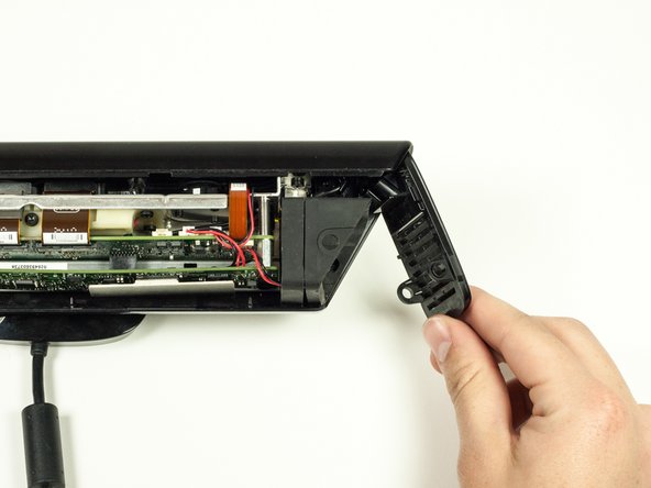
Remove the top portion of the case from the rest of the body.
-
Detach the side portions of the case from the body.
-
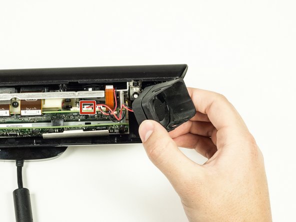
Remove the fan piece from the side of the body. Unplug it from the logic board to fully remove it.
-
-
Dieser Schritt ist noch nicht übersetzt. Hilf mit, ihn zu übersetzen!
-
Remove the bottom portion of the case by sliding it out from under the body.
-
-
Dieser Schritt ist noch nicht übersetzt. Hilf mit, ihn zu übersetzen!
-
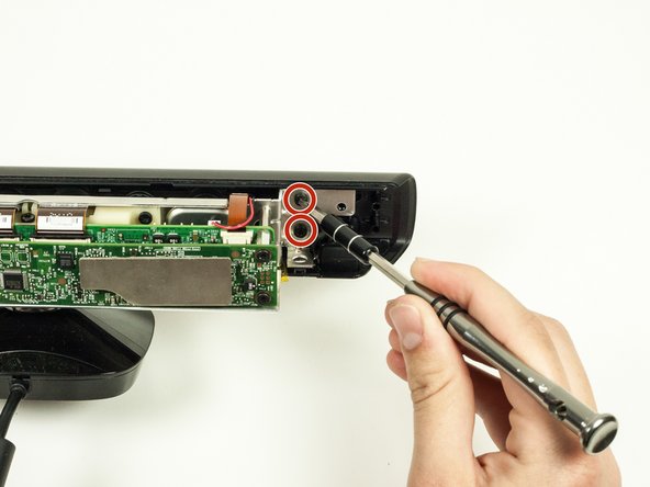
Remove the four 7mm T10 Torx screws (two on each side of the metal body).
-
-
Dieser Schritt ist noch nicht übersetzt. Hilf mit, ihn zu übersetzen!
-
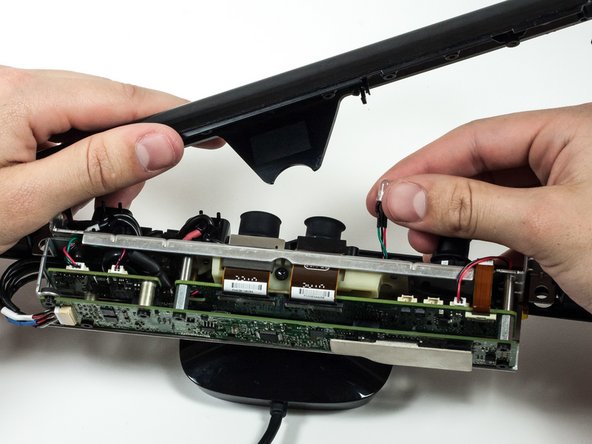
Remove the front portion of the case containing the lens coverings for the cameras.
-
The LED component is connected to the front portion of the case. To disconnect it, just pull it out of its plastic connector.
-
-
Dieser Schritt ist noch nicht übersetzt. Hilf mit, ihn zu übersetzen!
-
Unplug the microphone from motherboard.
-
-
-
Dieser Schritt ist noch nicht übersetzt. Hilf mit, ihn zu übersetzen!
-
Pull off the microphone panel and snake the cable that was connected to the motherboard through the hole on the camera panel.
-
-
Dieser Schritt ist noch nicht übersetzt. Hilf mit, ihn zu übersetzen!
-
Unscrew the seven 6.5mm T10 Torx screws.
-
-
Dieser Schritt ist noch nicht übersetzt. Hilf mit, ihn zu übersetzen!
-
Disconnect the bridge connecting the first and second layer of the motherboard.
-
Pull the first layer of the motherboard off.
-
-
Dieser Schritt ist noch nicht übersetzt. Hilf mit, ihn zu übersetzen!
-
Unplug the LED cable from the motherboard.
-
-
Dieser Schritt ist noch nicht übersetzt. Hilf mit, ihn zu übersetzen!
-
Unscrew the three 16.5mm screws using the 5mm Nut Driver.
-
Unscrew the one 6.5mm T10 Torx screw.
-
-
Dieser Schritt ist noch nicht übersetzt. Hilf mit, ihn zu übersetzen!
-
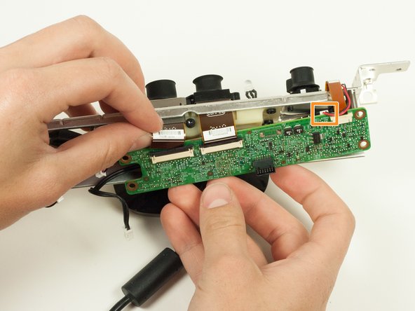
Remove the three ribbon cables.
-
Disconnect the left most camera from the motherboard.
-
-
Dieser Schritt ist noch nicht übersetzt. Hilf mit, ihn zu übersetzen!
-
Gently pull the LED out of the front of the metal casing. It should slide out easily.
-
-
Dieser Schritt ist noch nicht übersetzt. Hilf mit, ihn zu übersetzen!
-
Unscrew the four 7mm T10 Torx screws from the plastic body.
-
-
Dieser Schritt ist noch nicht übersetzt. Hilf mit, ihn zu übersetzen!
-
Remove the gold metal cylindrical piece from the metal body on the left side of the Kinect.
-
-
Dieser Schritt ist noch nicht übersetzt. Hilf mit, ihn zu übersetzen!
-
Carefully remove the top body portion of the Kinect from the stand by guiding the cable through the hole on the underside of the body, then lifting the body off of the plastic stand.
-
-
Dieser Schritt ist noch nicht übersetzt. Hilf mit, ihn zu übersetzen!
-
Unscrew the nine 7mm T6 Torx screws from the metal body. These hold the cameras in place.
-
-
Dieser Schritt ist noch nicht übersetzt. Hilf mit, ihn zu übersetzen!
-
Remove the plastic body from the metal body by sliding it off of the metal cylinders.
-
-
Dieser Schritt ist noch nicht übersetzt. Hilf mit, ihn zu übersetzen!
-
Remove the two cameras on the left (which are connected) by pulling their ribbon cables through their respective slots.
-
-
Dieser Schritt ist noch nicht übersetzt. Hilf mit, ihn zu übersetzen!
-
Remove the right camera from the metal body by sliding the cable through the hole it lies in.
-


Rückgängig: Ich habe diese Anleitung nicht absolviert.
3 weitere Nutzer:innen haben diese Anleitung absolviert.
Team

Cal Poly, Team 14-7, Amido Spring 2015 Mitglied von Cal Poly, Team 14-7, Amido Spring 2015
CPSU-AMIDO-S15S14G7
4 Mitglieder
6 Anleitungen geschrieben