Diese Version enthält möglicherweise inkorrekte Änderungen. Wechsle zur letzten geprüften Version.
Was du brauchst
-
Dieser Schritt ist noch nicht übersetzt. Hilf mit, ihn zu übersetzen!
-
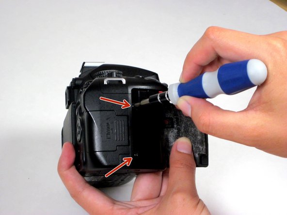
Remove the five screws around the camera using a Phillips #00 screwdriver.
-
-
Dieser Schritt ist noch nicht übersetzt. Hilf mit, ihn zu übersetzen!
-
Use your fingernail to gently peel back the black rubber thumb grip, attached to the chassis with a strong adhesive.
-
Use the Phillips #00 to remove the screw underneath the black rubber grip.
-
-
Dieser Schritt ist noch nicht übersetzt. Hilf mit, ihn zu übersetzen!
-
Carefully peel back the black rubber hand grip, which is attached to the chassis with a strong adhesive.
-
Use the Phillips #00 to remove two screws beneath the handgrip.
-
-
-
Dieser Schritt ist noch nicht übersetzt. Hilf mit, ihn zu übersetzen!
-
Using a spudger, pry off the diopter adjustment dial cover and remove the screw underneath.
-
Next, using a Phillips #00 screwdriver, remove the three Phillips screws around the viewfinder.
-
-
Dieser Schritt ist noch nicht übersetzt. Hilf mit, ihn zu übersetzen!
-
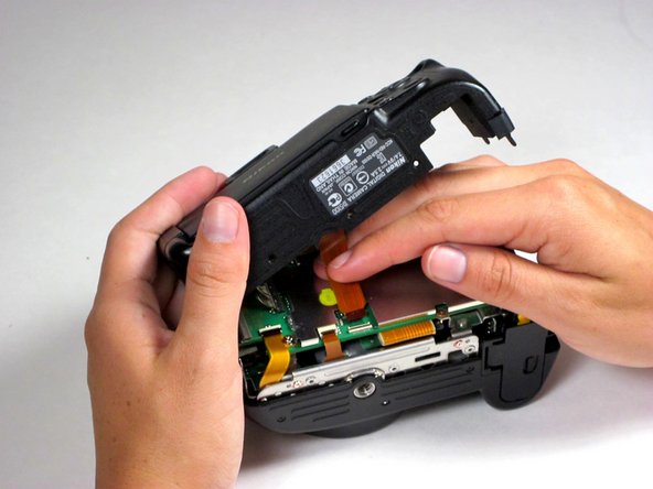
Carefully separate the rear panel from the camera body.
-
-
Dieser Schritt ist noch nicht übersetzt. Hilf mit, ihn zu übersetzen!
-
Remove the dark orange ribbon cable attaching the rear panel to the motherboard by flipping the black plastic clasp up, away from the motherboard, and pull the cable out of its white casing in the direction of the cable.
-
-
Dieser Schritt ist noch nicht übersetzt. Hilf mit, ihn zu übersetzen!
-
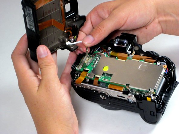
Remove the silver 16-pin cable by pulling gently upwards, away from the inside of the camera, until it separates from its port.
-
At this point, the rear panel is fully separated from the main body of the camera.
-


Rückgängig: Ich habe diese Anleitung nicht absolviert.
7 weitere Nutzer:innen haben diese Anleitung absolviert.
Team

Cal Poly, Team 10-54, Amido Spring 2014 Mitglied von Cal Poly, Team 10-54, Amido Spring 2014
CPSU-AMIDO-S14S10G54
4 Mitglieder
5 Anleitungen geschrieben