Diese Version enthält möglicherweise inkorrekte Änderungen. Wechsle zur letzten geprüften Version.
Was du brauchst
-
-
Entferne die beiden Kreuzschlitzschrauben, mit denen die Abdeckung des Akkus am Gehäuseunterteil befestigt ist.
-
Hebe die Abdeckung an und entferne sie vom Gehäuseunterteil.
-
-
-
Nimm einen Spudger (oder deinen Fingernagel) und hebe den Akku oben an.
-
Fasse den Akku und hebe ihn aus dem DSi heraus.
-
-
-
Zwei Schrauben befinden sich unter den beiden Gummifüßen (rot markiert).
-
Benutze die Spitze eines Spudger, um die Gummifüße aus dem Gehäuse zu lösen.
-
-
-
Entferne die Schrauben, mit denen das untere Gehäuse am DSi befestigt ist:
-
Sechs 5,2 mm Kreuzschlitzschrauben #00
-
Eine 2,7 mm Kreuzschlitzschraube #00
-
-
-
Setze den Spudger nahe der oberen rechten Ecke des DSi zwischen dem unteren Gehäuseteil und dem Bildschirm ein.
-
Führe den Spudger vorsichtig an der Kante des Außengehäuses entlang, damit eine Öffnung zwischen dem Hauptteil und dem Gehäuse entsteht.
-
Führe den Spudger weiter um das Gehäuse des DSi herum, bis der größte Teil des unteren Gehäuses entfernt wurde.
-
-
-
Hebe das untere Gehäuse vorsichtig an der Unterkante an.
-
Löse das Kabel der Lautstärkeregelung und der SD-Karte mit einem Spudger aus dem Anschluss auf der Hauptplatine.
-
Sobald das Kabel vollständig entfernt ist, lässt sich das gesamte Außengehäuse abnehmen.
-
-
-
Ziehe das WLAN-Modul an der Kante, die sich am nächsten zur Kopfhörerbuchse befindet, von der Hauptplatine ab.
-
-
-
-
Entferne den WLAN-Antennenstecker gerade aus seinem Anschluss auf der WLAN-Platine.
-
-
-
Heble den Stecker der Stromversorgung mit der Spudgerspitze aus seinem Anschluss auf der Hauptplatine heraus.
-
-
-
Klappe die Sicherungsbügel an folgenden drei ZIF-Anschlüssen mit dem Fingernagel oder der Kante eines Öffnungswerkzeugs hoch:
-
Unteres Touchscreenkabel
-
Unteres LCD-Kabel
-
Kabel der Stromversorgung
-
Wenn alle drei Sicherungsbügel geöffnet sind, ziehe die Kabel vorsichtig mit deinen Fingern oder einer Pinzette gerade aus ihren Anschlüssen heraus.
-
-
-
Klappe vorsichtig den Sicherungsbügel am Flachbandkabel zum Touchscreen mit dem Fingernagel oder der Kante eines Öffnungswerkzeugs nach oben.
-
Ziehe das Flachbandkabel zum Touchscreen mit der Spudgerspitze gerade aus seinem Anschluss heraus.
-
-
Dieser Schritt ist noch nicht übersetzt. Hilf mit, ihn zu übersetzen!
-
Use your fingernail or the edge of a plastic opening tool to carefully flip up the dual camera ribbon cable retaining flap.
-
Use the tip of a spudger to pull the dual camera ribbon cable straight out of its socket.
-
-
Dieser Schritt ist noch nicht übersetzt. Hilf mit, ihn zu übersetzen!
-
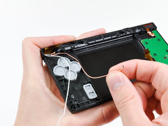
With the tip of a spudger, Pry the microphone antenna up off its socket on the motherboard.
-
-
Dieser Schritt ist noch nicht übersetzt. Hilf mit, ihn zu übersetzen!
-
Remove the following four Phillips screws securing the motherboard to the DSi framework.
-
Three longer screws.
-
One short screw.
-
Pull the microphone and Wi-Fi antenna cables out of the notch cut into the motherboard near the headphone jack.
-
-
Dieser Schritt ist noch nicht übersetzt. Hilf mit, ihn zu übersetzen!
-
Slightly lift the motherboard upwards to reveal the upper LCD ribbon cable above the ABXY buttons .
-
Use your fingernail or the edge of a plastic opening tool to carefully flip up the upper LCD ribbon cable retaining flap.
-
Remove the motherboard from the DSi.
-
-
Dieser Schritt ist noch nicht übersetzt. Hilf mit, ihn zu übersetzen!
-
Use the tip of a spudger to pry the metal backing of the lower LCD up from the DSi's framework.
-
Lift the lower LCD assembly out of the DSi.
-
-
Dieser Schritt ist noch nicht übersetzt. Hilf mit, ihn zu übersetzen!
-
Use a pushpin to remove the four plastic screw covers (highlighted in red) on the front bezel.
-
-
Dieser Schritt ist noch nicht übersetzt. Hilf mit, ihn zu übersetzen!
-
Remove the four Phillips screws securing the rear bezel to the front bezel.
-
-
Dieser Schritt ist noch nicht übersetzt. Hilf mit, ihn zu übersetzen!
-
Using two hands, gently slide the rear bezel upwards.
-
Lift the rear bezel straight up out of the DSi.
-
-
Dieser Schritt ist noch nicht übersetzt. Hilf mit, ihn zu übersetzen!
-
De-route the Wi-Fi and microphone cables from the slot molded into the bottom front bezel.
-
-
Dieser Schritt ist noch nicht übersetzt. Hilf mit, ihn zu übersetzen!
-
Use the tip of a spudger to gently lift the microphone out of its housing in the top front bezel.
-
De-route the microphone cable through the hinge and remove it from the DSi.
-


Rückgängig: Ich habe diese Anleitung nicht absolviert.
Ein:e weitere:r Nutzer:in hat diese Anleitung absolviert.

2 Kommentare
Love the guide! If your mic still doesn’t work look into the headphone/mic jack and see if the two pins are pulled down inside. If they are stuck up then the mic will default to the jack mic input even if there’s nothing in the socket. I pulled mine down with the Ifixit tweezers and this fixed my mic problems.
Hey this worked for me thanks! I wonder how you found out lol