Diese Version enthält möglicherweise inkorrekte Änderungen. Wechsle zur letzten geprüften Version.
Was du brauchst
-
Dieser Schritt ist noch nicht übersetzt. Hilf mit, ihn zu übersetzen!
-
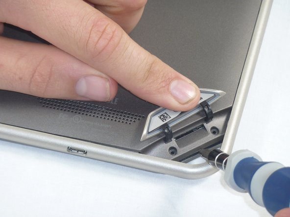
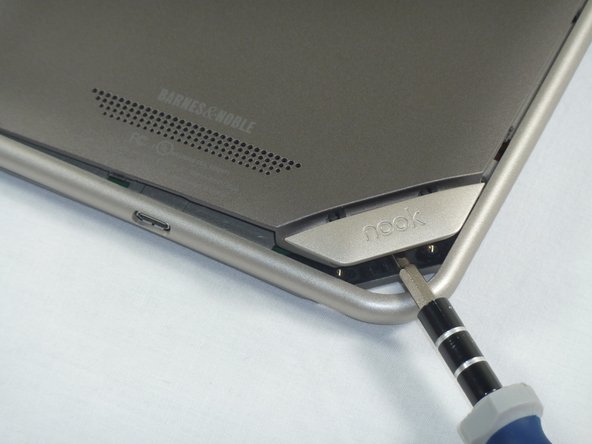
Lift the flap that reads "Nook" to reveal the tape that is underneath. Remove the memory card if one is present.
-
Remove the tape covering the round holes to reveal two T5 Torx screws.
-
Remove the two T5 Torx screws securing the back cover.
-
-
Dieser Schritt ist noch nicht übersetzt. Hilf mit, ihn zu übersetzen!
-
Insert the flat end of a spudger between the front panel and the rear assembly.
-
Use a spudger to lift the the back panel from the rest of the Nook.
-
-
Dieser Schritt ist noch nicht übersetzt. Hilf mit, ihn zu übersetzen!
-
Slide the spudger around the edges of the Nook to loosen the back panel.
-
-
-
Dieser Schritt ist noch nicht übersetzt. Hilf mit, ihn zu übersetzen!
-
Pull the back panel off the Nook.
-
-
Dieser Schritt ist noch nicht übersetzt. Hilf mit, ihn zu übersetzen!
-
Using the T5 Torx screwdriver, remove the ten T5 screws from around the edges of the silver midframe.
-
-
Dieser Schritt ist noch nicht übersetzt. Hilf mit, ihn zu übersetzen!
-
Using a spudger or plastic opening tool, carefully pry the screen bezel away from the silver midframe.
-
-
Dieser Schritt ist noch nicht übersetzt. Hilf mit, ihn zu übersetzen!
-
Lift up the foam pad at the corner of the battery to reveal the battery connector.
-
Use a spudger or plastic opening tool to disconnect the battery cable from the motherboard.
-
-
Dieser Schritt ist noch nicht übersetzt. Hilf mit, ihn zu übersetzen!
-
Lift up the foam that covers the power connector and volume connector.
-
Disconnect the power and volume cables from their sockets on the motherboard.
-
-
Dieser Schritt ist noch nicht übersetzt. Hilf mit, ihn zu übersetzen!
-
Carefully lift the silver midframe away from the motherboard and display assembly.
-
-
Dieser Schritt ist noch nicht übersetzt. Hilf mit, ihn zu übersetzen!
-
Using your hands pull the square speaker assembly component off the motherboard.
-
-
Dieser Schritt ist noch nicht übersetzt. Hilf mit, ihn zu übersetzen!
-
Now place the new speaker assembly component back in the same square location.
-
As Step 12 mentions, make sure to realign the speaker assembly correctly in the square.
-


Rückgängig: Ich habe diese Anleitung nicht absolviert.
Ein:e weitere:r Nutzer:in hat diese Anleitung absolviert.
Team

Cal Poly, Team 1-4, Propen Fall 2012 Mitglied von Cal Poly, Team 1-4, Propen Fall 2012
CPSU-PROPEN-F12S1G4
4 Mitglieder
14 Anleitungen geschrieben