Diese Version enthält möglicherweise inkorrekte Änderungen. Wechsle zur letzten geprüften Version.
Was du brauchst
-
Dieser Schritt ist noch nicht übersetzt. Hilf mit, ihn zu übersetzen!
-
Slide the lock switch to the right so that it is in the unlocked position.
-
Use your finger to slide the battery hatch in the direction of the downward arrow so that the hatch is open.
-
-
Dieser Schritt ist noch nicht übersetzt. Hilf mit, ihn zu übersetzen!
-
Open the battery hatch and then the black cover to expose the battery compartment.
-
Remove the battery.
-
-
Dieser Schritt ist noch nicht übersetzt. Hilf mit, ihn zu übersetzen!
-
Using the Phillips #00 screwdriver, remove the two 2.8 mm screws located under the hatch.
-
-
Dieser Schritt ist noch nicht übersetzt. Hilf mit, ihn zu übersetzen!
-
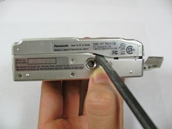
Use the Phillips #00 screwdriver to remove the three 2.8 mm screws on the bottom of the camera.
-
-
-
Dieser Schritt ist noch nicht übersetzt. Hilf mit, ihn zu übersetzen!
-
Use the Phillips #00 screwdriver to remove the two 2.8 mm screws on the side of the camera.
-
-
Dieser Schritt ist noch nicht übersetzt. Hilf mit, ihn zu übersetzen!
-
Use a spudger to pry open the case at all sides.
-
-
Dieser Schritt ist noch nicht übersetzt. Hilf mit, ihn zu übersetzen!
-
Use your fingers to carefully remove the back casing from the front of the camera.
-
-
Dieser Schritt ist noch nicht übersetzt. Hilf mit, ihn zu übersetzen!
-
Place the camera on a flat surface with the front side facing down.
-
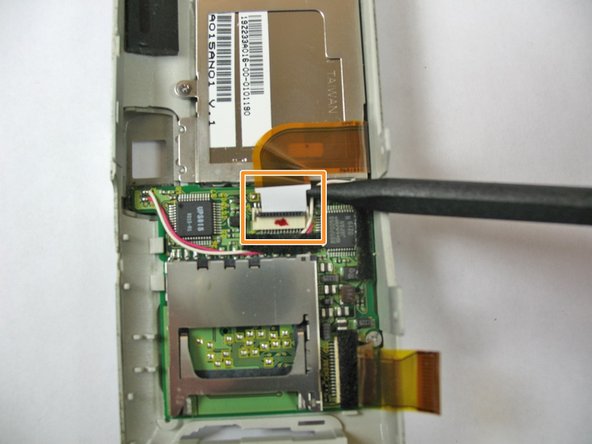
Use the spudger to flip up the retaining flap and slide the ribbon cable out of the connector.
-
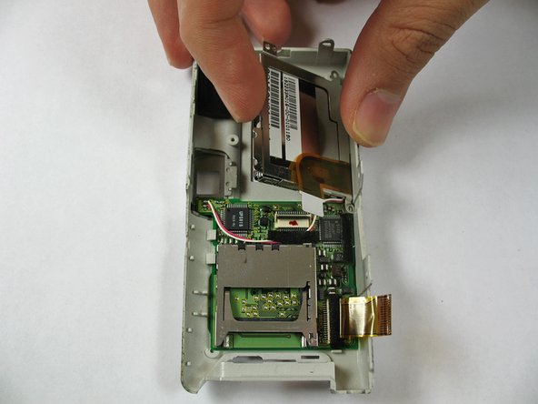
Hold down on the camera's metal casing with one hand. Using your other hand, remove the back case from the rest of the camera.
-
-
Dieser Schritt ist noch nicht übersetzt. Hilf mit, ihn zu übersetzen!
-
Use a spudger to lift the screen ZIF connector tab.
-
Use the back of the spudger to push the ribbon cable free.
-
-
Dieser Schritt ist noch nicht übersetzt. Hilf mit, ihn zu übersetzen!
-
Use the screwdriver to remove the four 2.4 mm Phillips screws.
-
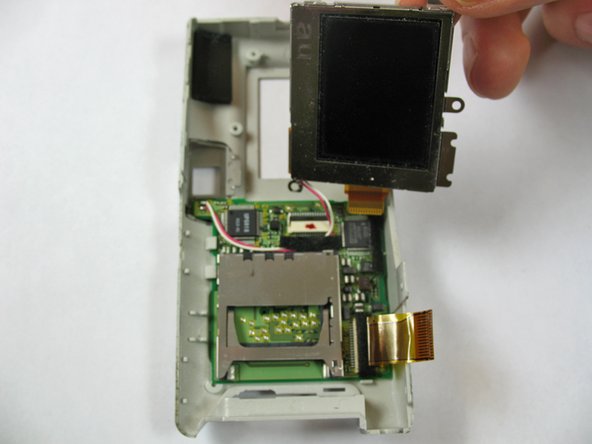
Lift up the LCD screen from the front case.
-
-
Dieser Schritt ist noch nicht übersetzt. Hilf mit, ihn zu übersetzen!
-
Remove the LCD screen from its case.
-
-
Dieser Schritt ist noch nicht übersetzt. Hilf mit, ihn zu übersetzen!
-
Locate the wire connecting the LCD screen to the motherboard.
-
Use the soldering iron to desolder the wire.
-
Use the soldering iron to solder wires from new LCD screen to the circuit board.
-


Rückgängig: Ich habe diese Anleitung nicht absolviert.
Ein:e weitere:r Nutzer:in hat diese Anleitung absolviert.
Team

Cal Poly, Team 7-35, Regan Winter 2011 Mitglied von Cal Poly, Team 7-35, Regan Winter 2011
CPSU-REGAN-W11S7G35
4 Mitglieder
10 Anleitungen geschrieben