Diese Version enthält möglicherweise inkorrekte Änderungen. Wechsle zur letzten geprüften Version.
Was du brauchst
-
Dieser Schritt ist noch nicht übersetzt. Hilf mit, ihn zu übersetzen!
-
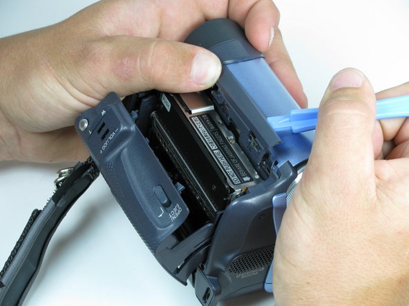
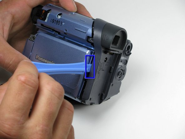
Locate the blue plastic tool opener, then remove both the round record/playback and record/power control knobs by prying it open from the camcorder.
-
-
Dieser Schritt ist noch nicht übersetzt. Hilf mit, ihn zu übersetzen!
-
Open the tape compartment.
-
Then flip the camcorder and locate two 4.5mm screws that are horizontal from each other and about 2 inches apart using a #00 Phillips screwdriver.
-
-
Dieser Schritt ist noch nicht übersetzt. Hilf mit, ihn zu übersetzen!
-
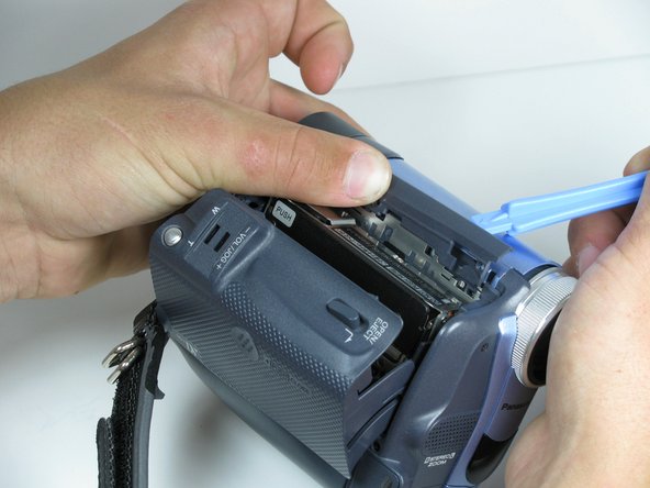
Use the blue plastic opening tool to remove the gray trim piece by prying it from top of the camcorder.
-
-
Dieser Schritt ist noch nicht übersetzt. Hilf mit, ihn zu übersetzen!
-
Rotate the camcorder so that the eye piece is facing you.
-
Remove the four black 4.5mm screws, sitting behind the battery.
-
Remove the 5th screw to the right of the battery dock.
-
Remove the battery by gently pulling away from the camcorder.
-
-
Dieser Schritt ist noch nicht übersetzt. Hilf mit, ihn zu übersetzen!
-
Rotate the camcorder so that the tape compartment is facing you.
-
Remove the single 4.5mm black screw above the hook for the hand strap.
-
Rotate the camcorder so that the lens is facing you.
-
Remove the single 4.5mm black screw from the front panel.
-
-
-
Dieser Schritt ist noch nicht übersetzt. Hilf mit, ihn zu übersetzen!
-
Rotate the camcorder so that the bottom is facing towards you.
-
Remove the single remaining 4.5mm black screw from the bottom.
-
Remove the four silver 4.5mm screws from the body.
-
-
Dieser Schritt ist noch nicht übersetzt. Hilf mit, ihn zu übersetzen!
-
Open the LCD screen on the side of the camcorder.
-
Using a #00 screwdriver, remove the two 4.5mm silver screws located on either side of the hinge of the LCD screen.
-
-
Dieser Schritt ist noch nicht übersetzt. Hilf mit, ihn zu übersetzen!
-
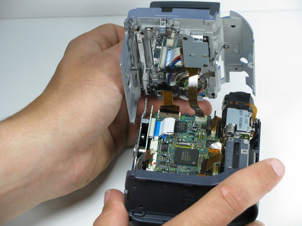
This should come apart with relative ease, however a plastic opening tool may help remove the panel.
-
-
Dieser Schritt ist noch nicht übersetzt. Hilf mit, ihn zu übersetzen!
-
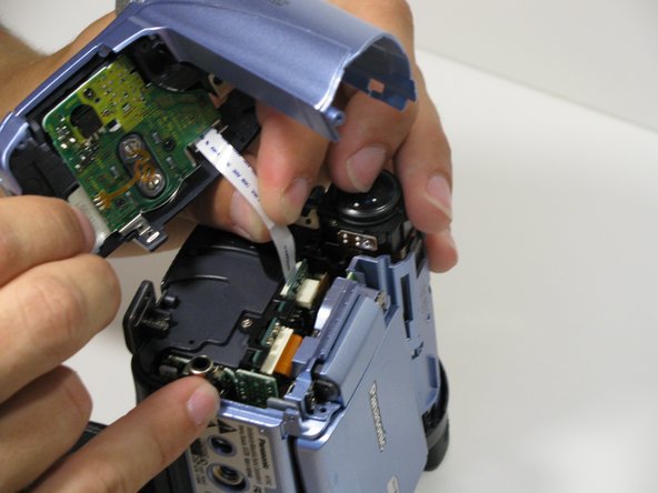
Using your fingers, carefully pull the ribbon cable away from the logic board.
-
-
Dieser Schritt ist noch nicht übersetzt. Hilf mit, ihn zu übersetzen!
-
Remove the indicated 4.5mm screws from the LCD side of the camera.
-
-
Dieser Schritt ist noch nicht übersetzt. Hilf mit, ihn zu übersetzen!
-
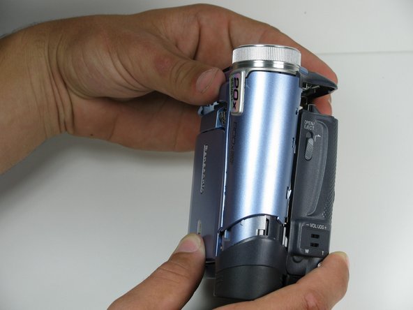
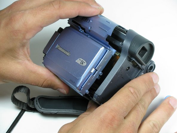
Place a plastic opening tool under the bottom of the blue panel beneath the camcorder.
-
Using two tools may be useful, if difficult.
-
Move the plastic opening tool up the side of the camcorder as shown. Carefully separate the LCD panel from the rest of the camcorder.
-
Remove the panel from the camcorder.
-
-
Dieser Schritt ist noch nicht übersetzt. Hilf mit, ihn zu übersetzen!
-
There may be multiple ribbon cables attached to the same point on the logic board.
-
-
Dieser Schritt ist noch nicht übersetzt. Hilf mit, ihn zu übersetzen!
-
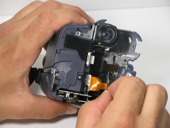
Remove two 4.5mm silver tripod mount screws.
-
-
Dieser Schritt ist noch nicht übersetzt. Hilf mit, ihn zu übersetzen!
-
Remove tripod mount carefully by prying it off with a plastic opening tool.
-


Team

Cal Poly, Team 7-9, Maness Spring 2010 Mitglied von Cal Poly, Team 7-9, Maness Spring 2010
CPSU-MANESS-S10S7G9
4 Mitglieder
15 Anleitungen geschrieben