Einleitung
Contaminates can sometimes get stuck in the curtain blades slow the movement of the shutter. Disassembly, cleaning, and reassembly can often restore proper operation and timing of the shutter.
Was du brauchst
-
-
Remove the rubber decorative cap. It is attached with contact cement underneath. Isopropyl Alcohol may be used to soften the adhesive.
-
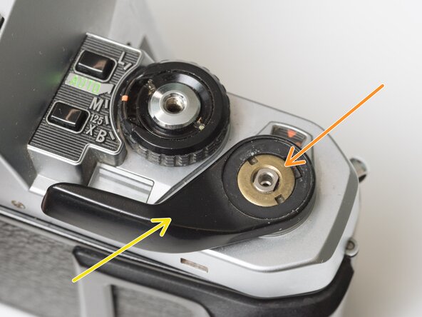
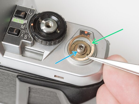
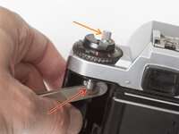
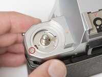
Unscrew the lock nut using a spanner wrench. The lock nut is reverse threaded.
-
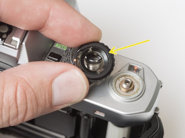
Lift off the advance lever.
-
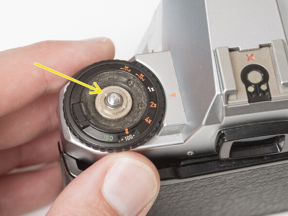
Remove the spring washer.
-
Remove one shim washer.
-
-
-
Set the mode dial to the 'L' position.
-
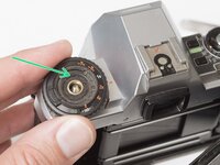
Use a spanner wrench to unscrew the dial lock nut.
-
Lift off the mode dial.
-
-
-
Place a rigid object in the fork.
-
Unscrew the rewind lever.
-
Use a spanner wrench to remove the lock nut.
-
Lift off the exposure compensation dial.
-
-
-
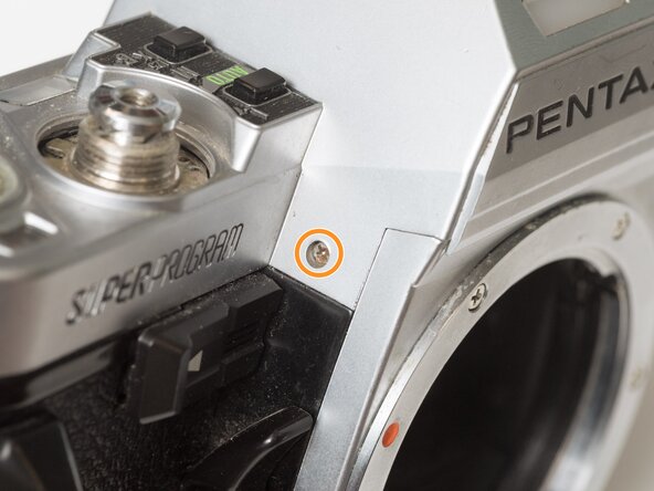
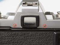
Remove two screws on either side of the eye piece.
-
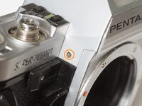
Remove two screws on either side of the lens mount.
-
-
-
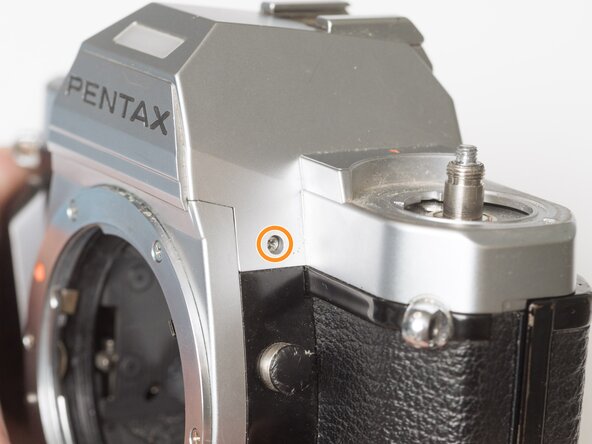
Remove one screw by the exposure compensation dial.
-
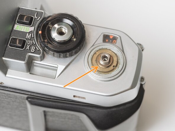
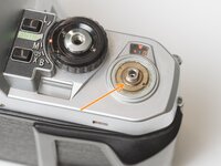
Use a spanner wrench to remove the lock nut under the advance lever.
-
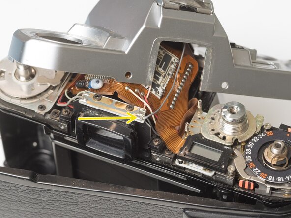
Lift off the top cover slowly. It is still attached by one wire.
-
Unsolder one gray flash sync wire.
-
-
-
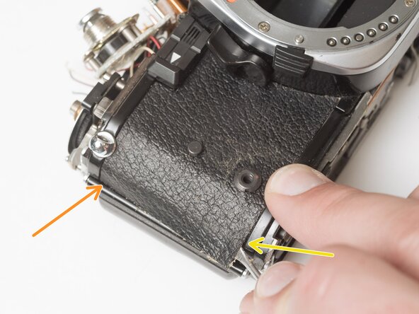
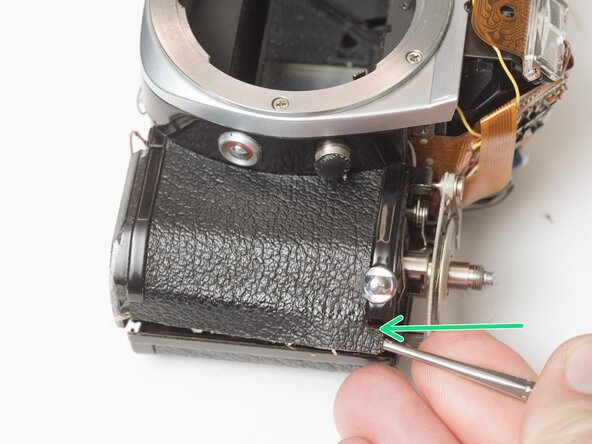
Use a nickel or other large coin to remove the hand grip.
-
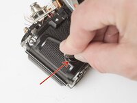
Drip isopropyl alcohol along the edge of the leatherette to soften the adhesive.
-
Use a dull scraper to lift one corner and pull off the panel.
-
Repeat on the rewind side of the camera.
-
-
-
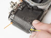
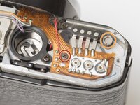
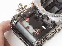
Remove one M1.7 x 4.5 mm screw.
-
Remove one slotted screw.
-
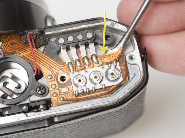
Use isopropyl alcohol to soften the adhesive under the flex PCB.
-
Gently lift the PCB until it is free from the camera body.
-
-
-
-
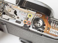
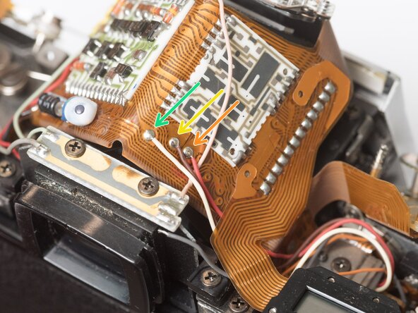
Unsolder one red wire.
-
Unsolder one light blue wire.
-
Unsolder one orange wire.
-
Unsolder one purple wire.
-
-
-
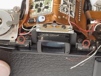
Remove one M1.7 x 4.5 mm screw.
-
Remove one M1.7 x 5 mm screw.
-
Remove one countersunk M1.7 x 5.5 mm screw.
-
Lift the contact terminal free from its seat.
-
Remove the tripod mount.
-
-
-
Remove one slotted screw.
-
Remove one M1.7 x 4 mm screw.
-
Loosen one slotted screw (this will remain connected to the assembly).
-
Lift the ISO resistor assembly off the rewind post. It is still attached by a flex PCB.
-
-
-
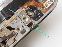
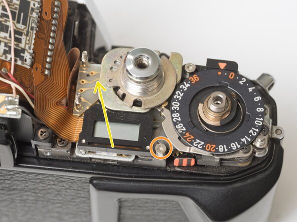
Remove one M1.7 x 2.5 mm screw. It is only accessible when the mode dial is in the 'L' position.
-
Remove one crosshead screw.
-
Lift the LCD out of the way. It is still attached by a flex PCB.
-
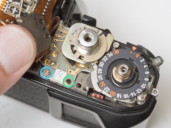
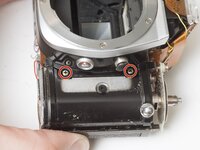
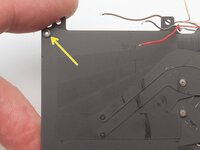
Remove one M1.7 x 2.5 mm screw.
-
Remove one slotted screw.
-
-
-
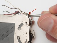
Unsolder one gray wire.
-
Unsolder one red wire.
-
Unsolder one brown wire.
-
Unsolder one white wire.
-
-
-
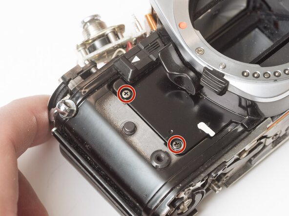
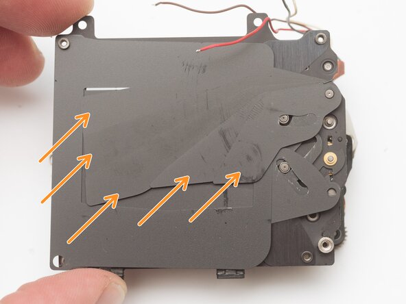
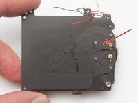
Remove two M1.7 x 2.5 mm screws.
-
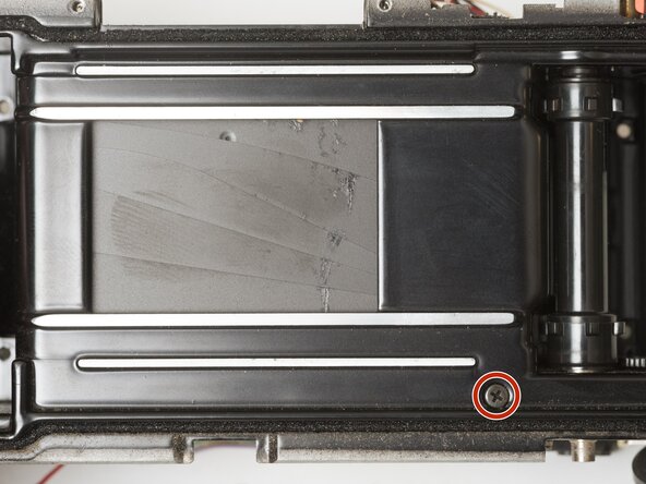
Remove one M1.7 x 3.5 mm screw under the bottom plate.
-
-
-
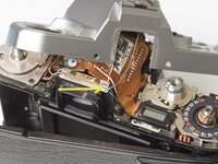
Wind the shutter
-
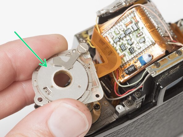
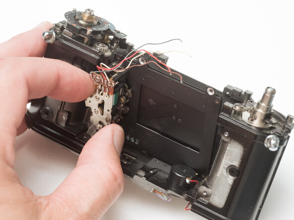
Make sure the mode dial unit and ISO selector unit are free from their mounting points.
-
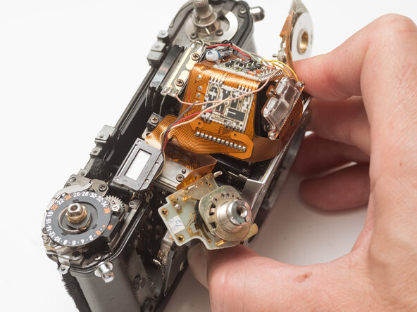
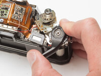
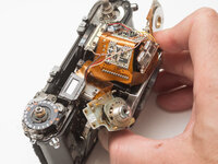
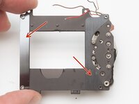
Wiggle the mirror box and front board free.
-
Watch for wire snags as you pull it free.
-
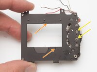
Check for loose shim washers on the front board and note their position.
-
-
-
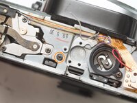
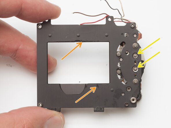
Shutter should be in the charged state.
-
Mirror box should be in released state.
-
Pay close attention to wire routing during install.
-
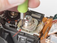
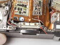
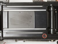
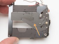
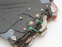
To test the actuation of the mirror and shutter, wind the camera, then insert a tool into this slot and push the release lever to the left.
-
-
-
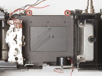
Remove three M1.7 x 3 mm screws.
-
Lift shutter unit out of camera body.
-
-
-
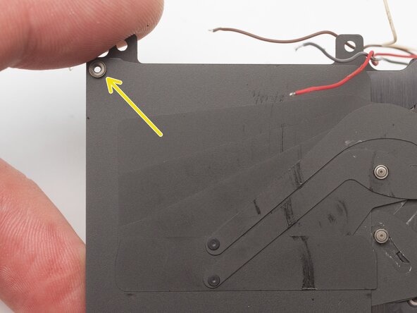
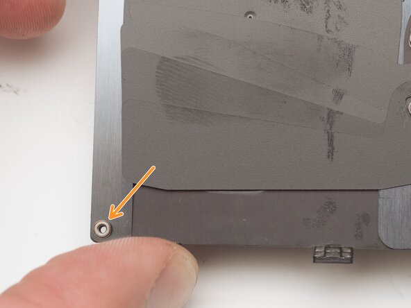
Remove old foam seals.
-
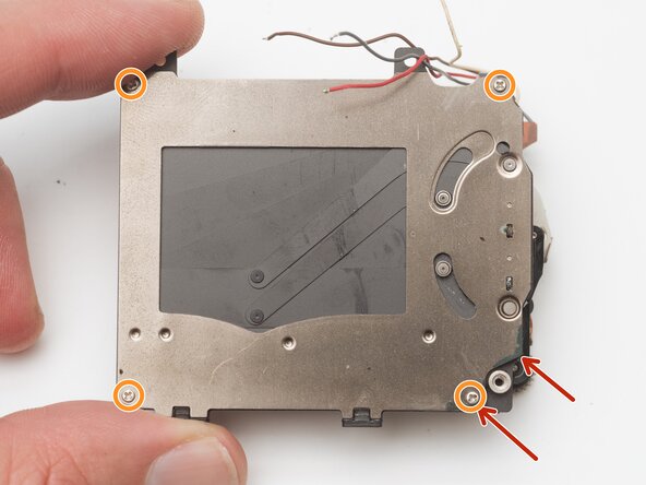
Remove four M1.4 x 2.4 mm screws.
-
Remove top spacer bushing.
-
-
-
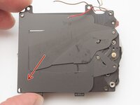
Remove closing curtain linkage.
-
Remove five curtain blades.
-
-
-
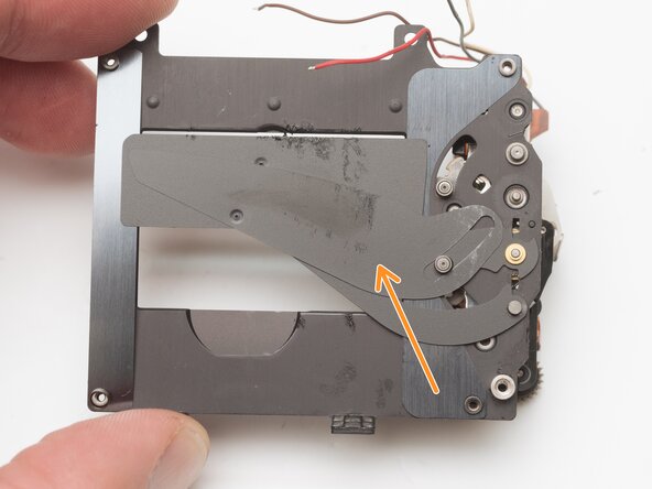
Remove curtain separator.
-
Remove lower separator bushing.
-
-
-
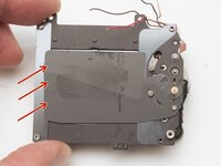
Remove three curtain blades.
-
Remove opening curtain linkage.
-
-
-
Remove two curtain guides.
-
Clean any residue from the shutter frame and blades using isopropyl alcohol or other solvent.
-
Clean the curtain pivots.
-
Remove degraded rubber dampers and clean the surrounding area. They do not need to be replaced.
-


To reassemble your device, follow these instructions in reverse order.