Diese Version enthält möglicherweise inkorrekte Änderungen. Wechsle zur letzten geprüften Version.
Was du brauchst
-
-
Die vier 6,4 mm Schrauben auf der Rückseite mit einem Phillips #00 Schraubendreher entfernen.
-
-
-
Öffne den Zubehörslot mit einem Fingernagel oder Spudger.
-
Entferne die zwei 5,4 mm Schrauben mit einem Phillips #00 Schraubendreher.
-
-
-
Trenne die Front- und Rückseite, indem du ein Plastic Opening Tool an der Seite des Gerätes einführst.
-
Vorsichtig um das Gerät herum gehen und aufhebeln.
-
-
-
Vorsichtig die beiden Seiten trennen und auf die Batterie- und Touchscreen-Controller-Verbindungen, welche die Seiten zusammenhalten, achten.
-
-
-
Dieser Schritt ist noch nicht übersetzt. Hilf mit, ihn zu übersetzen!
-
Pry up the left shoulder button casing with a spudger.
-
Remove the left shoulder button casing.
-
-
Dieser Schritt ist noch nicht übersetzt. Hilf mit, ihn zu übersetzen!
-
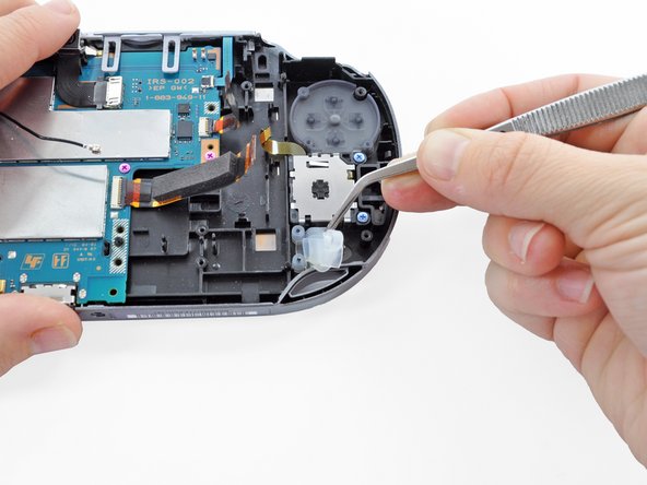
Remove the translucent, plastic left shoulder button cover.
-
-
Dieser Schritt ist noch nicht übersetzt. Hilf mit, ihn zu übersetzen!
-
Release the left shoulder button flex cable socket by using a spudger to pry open the tab.
-
Using tweezers, slide the flex cable out of the socket. Do not pull on the black tab! Instead, pull the thin flex cable away from the connector (to the left in this image).
-
-
Dieser Schritt ist noch nicht übersetzt. Hilf mit, ihn zu übersetzen!
-
Using a spudger, gently peel up the left shoulder button from the light adhesive connecting it to casing.
-
-
Dieser Schritt ist noch nicht übersetzt. Hilf mit, ihn zu übersetzen!
-
Using a spudger, lift and release the tab on the ZIF socket sitting on the SIM card reader.
-
Carefully pull the flex cable out of the ZIF socket, and rest it out of the way.
-
-
Dieser Schritt ist noch nicht übersetzt. Hilf mit, ihn zu übersetzen!
-
Use a spudger to release the tab between the SIM card reader and the back casing assembly.
-
Lift the SIM card reader off the back casing assembly.
-
-
Dieser Schritt ist noch nicht übersetzt. Hilf mit, ihn zu übersetzen!
-
Release the plastic tab on the small flex cable socket by prying it up with a spudger.
-
Using tweezers, gently remove the small flex cable from the socket, and rest it out of the way.
-
-
Dieser Schritt ist noch nicht übersetzt. Hilf mit, ihn zu übersetzen!
-
Use a spudger to lift up the tab on the large ZIF socket.
-
Gently pull the flex cable out of the ZIF socket, and rest it out of the way.
-
-
Dieser Schritt ist noch nicht übersetzt. Hilf mit, ihn zu übersetzen!
-
Disconnect the white Wi-Fi antenna cable with a spudger.
-
Remove the Wi-Fi antenna cable.
-
-
Dieser Schritt ist noch nicht übersetzt. Hilf mit, ihn zu übersetzen!
-
Using a Phillips #00 screwdriver, remove the six screws on the two metal brackets:
-
Two 5.0mm, blue screws on the L-bracket securing the upper left button board to the motherboard.
-
Four 5.0mm, blue screws on the square bracket securing the lower left button board to the motherboard.
-
-
Dieser Schritt ist noch nicht übersetzt. Hilf mit, ihn zu übersetzen!
-
Starting from the upper left corner, use a spudger to pry up and remove the left button board.
-
-
Dieser Schritt ist noch nicht übersetzt. Hilf mit, ihn zu übersetzen!
-
Using tweezers, peel up and remove the PS button.
-


Rückgängig: Ich habe diese Anleitung nicht absolviert.
7 weitere Nutzer:innen haben diese Anleitung absolviert.

