Diese Version enthält möglicherweise inkorrekte Änderungen. Wechsle zur letzten geprüften Version.
Was du brauchst
-
Dieser Schritt ist noch nicht übersetzt. Hilf mit, ihn zu übersetzen!
-
Use a Phillips #00 driver to remove four screws (3mm) on the left side of the camera. Keep all screws for reassembly.
-
Directly on the bottom of the camera there are 3 screws, unscrew all with a Phillips #00 driver.
-
Unscrew two screws on the right side of the camera with a Phillips #00 driver.
-
-
Dieser Schritt ist noch nicht übersetzt. Hilf mit, ihn zu übersetzen!
-
Locate the battery door on the bottom of the camera. Then slide the battery door open using the iFixit opening tool.
-
Gently open the back cover of camera.
-
-
Dieser Schritt ist noch nicht übersetzt. Hilf mit, ihn zu übersetzen!
-
Locate where the LCD screen ribbon is attached to the logic board.
-
Using the ifixit opening tool, push the black tab connecting the LCD screen ribbon to the logic board away from you.
-
Gently pull the ribbon away from the logic board with thumb and index fingers.
-
-
-
Dieser Schritt ist noch nicht übersetzt. Hilf mit, ihn zu übersetzen!
-
Using the Phillips #00 screwdriver, unscrew and remove the (3mm) screw on the bottom of the logic board above the tripod mount. Keep the screw for reassembly.
-
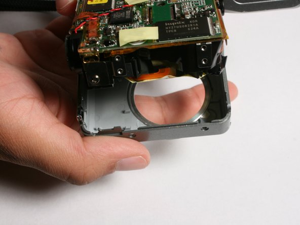
Gently pull the front of the case off.
-
-
Dieser Schritt ist noch nicht übersetzt. Hilf mit, ihn zu übersetzen!
-
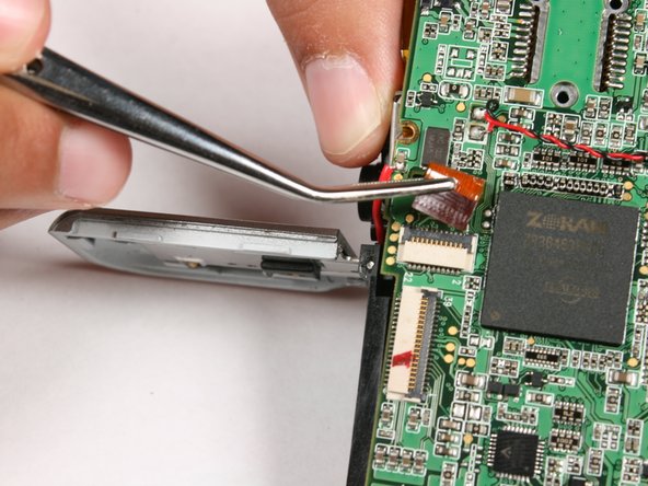
Locate the black patch covering the ribbon that connects the zoom lens to the logic board.
-
Carefully remove the black patch using tweezers.
-
-
Dieser Schritt ist noch nicht übersetzt. Hilf mit, ihn zu übersetzen!
-
Using tweezers gently lift the black tab that holds the zoom lens ribbon in place.
-
Gently remove the zoom lens ribbon.
-
-
Dieser Schritt ist noch nicht übersetzt. Hilf mit, ihn zu übersetzen!
-
Use the Phillips #00 screwdriver and unscrew then remove the three (3mm) screws shown on the back of the logic board.
-
On the left side of the logic board use the same screwdriver. Unscrew and remove the 3mm screw. Keep all screws for reassembly.
-
-
Dieser Schritt ist noch nicht übersetzt. Hilf mit, ihn zu übersetzen!
-
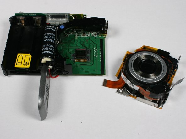
It is now safe for you to remove the zoom lens.
-
To reassemble the device, follow these steps in reverse.
-


Team

Cal Poly, Team 3-4, Johann Summer 2010 Mitglied von Cal Poly, Team 3-4, Johann Summer 2010
CPSU-JOHANN-R10S3G4
4 Mitglieder
8 Anleitungen geschrieben