Diese Version enthält möglicherweise inkorrekte Änderungen. Wechsle zur letzten geprüften Version.
Was du brauchst
-
Dieser Schritt ist noch nicht übersetzt. Hilf mit, ihn zu übersetzen!
-
Use a coin to turn the battery locking screw 90 degrees clockwise.
-
Lift the battery out of the computer.
-
-
Dieser Schritt ist noch nicht übersetzt. Hilf mit, ihn zu übersetzen!
-
Remove the following 10 screws:
-
Two 3 mm Phillips in the battery compartment, on either side of the battery contacts.
-
Four 3 mm Phillips around the memory compartment.
-
Four 16 mm Phillips along the hinge.
-
-
Dieser Schritt ist noch nicht übersetzt. Hilf mit, ihn zu übersetzen!
-
Remove the memory compartment cover.
-
Remove the two 12 mm Phillips screws on the Aluminum bracket at the top of the memory compartment.
-
-
Dieser Schritt ist noch nicht übersetzt. Hilf mit, ihn zu übersetzen!
-
Rotate the computer 90 degrees clockwise so the power receptacle faces you.
-
Remove the three 3 mm Phillips screws along the edge of the lower case.
-
-
Dieser Schritt ist noch nicht übersetzt. Hilf mit, ihn zu übersetzen!
-
Turn the computer 90 degrees clockwise so the hinge faces you.
-
Remove the lower 5 mm Phillips screw on each side of the hinge (two total).
-
-
Dieser Schritt ist noch nicht übersetzt. Hilf mit, ihn zu übersetzen!
-
Rotate the computer 90 degrees clockwise so the ports face you.
-
Remove the three 3 mm Phillips screws along the edge of the lower case.
-
When replacing these screws, you must install them in the correct order. Begin by installing the screw closest to the display hinge, then work your way toward the front of the computer. Also, be careful not to put the screws in the two holes on either side of the video out port.
-
-
-
Dieser Schritt ist noch nicht übersetzt. Hilf mit, ihn zu übersetzen!
-
Turn the computer over and open the display.
-
Remove the two 4.2 mm long, 1.5 mm hex screws at the top corners of the upper case (two total).
-
-
Dieser Schritt ist noch nicht übersetzt. Hilf mit, ihn zu übersetzen!
-
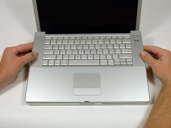
Grasp the back corners of the upper case and pull up.
-
Lift the back of the case up and work your fingers along the sides, freeing the case as you go. Once you have freed the sides, you may need to rock the case up and down to free the front of the upper case.
-
-
Dieser Schritt ist noch nicht übersetzt. Hilf mit, ihn zu übersetzen!
-
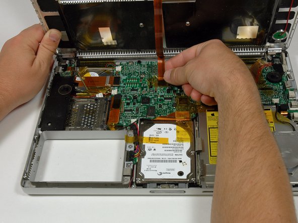
Rotate the upper case up and toward the screen, so that the upper case rests against it.
-
-
Dieser Schritt ist noch nicht übersetzt. Hilf mit, ihn zu übersetzen!
-
Remove the amber tape securing the trackpad ribbon to the logic board.
-
Disconnect the trackpad ribbon from the logic board by pulling up on the connector.
-
Remove the upper case from the computer.
-
-
Dieser Schritt ist noch nicht übersetzt. Hilf mit, ihn zu übersetzen!
-
Remove the two 3 mm Phillips screws securing the left ambient light sensor. One is silver and one is black, or both black.
-
Disconnect the cable from the Logic board and remove the left ambient light sensor from your computer.
-
-
Dieser Schritt ist noch nicht übersetzt. Hilf mit, ihn zu übersetzen!
-
Remove the 4 mm hex nut securing the left speaker.
-
-
Dieser Schritt ist noch nicht übersetzt. Hilf mit, ihn zu übersetzen!
-
Disconnect the left speaker cable.
-
-
Dieser Schritt ist noch nicht übersetzt. Hilf mit, ihn zu übersetzen!
-
Remove the four Phillips screws from the PC card cage.
-
-
Dieser Schritt ist noch nicht übersetzt. Hilf mit, ihn zu übersetzen!
-
Disconnect the PC card cable from the logic board.
-
-
Dieser Schritt ist noch nicht übersetzt. Hilf mit, ihn zu übersetzen!
-
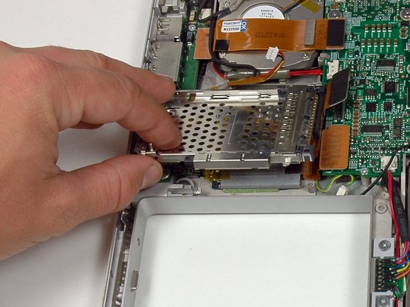
Lift the PC card cage up and remove it from the computer.
-