Diese Version enthält möglicherweise inkorrekte Änderungen. Wechsle zur letzten geprüften Version.
Was du brauchst
-
Dieser Schritt ist noch nicht übersetzt. Hilf mit, ihn zu übersetzen!
-
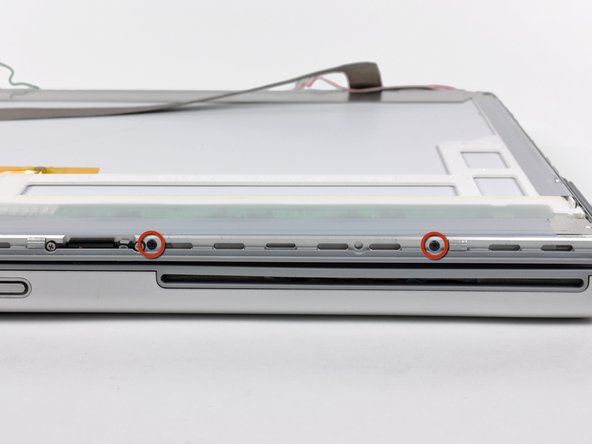
Remove the two 6.3 mm Phillips screws near the lower left and right corners of the display.
-
-
Dieser Schritt ist noch nicht übersetzt. Hilf mit, ihn zu übersetzen!
-
Insert the flat end of a spudger between the rear display bezel and the plastic rim attached to the front display bezel near the lower right corner of the display.
-
While carefully prying the rear display bezel away from the display assembly, use a small flathead screwdriver to pry the small steel clip nearest the bottom right corner of the display away from the edge of the front display bezel.
-
Repeat the above procedure until you've released all the clips along the right side of the display.
-
-
Dieser Schritt ist noch nicht übersetzt. Hilf mit, ihn zu übersetzen!
-
Slightly lift the recently-freed corner of the rear display bezel to separate the clips with a spudger along the span of the clutch hinges.
-
-
Dieser Schritt ist noch nicht übersetzt. Hilf mit, ihn zu übersetzen!
-
Insert the flat end of a spudger between the rear display bezel and the plastic surround of the front display bezel near the lower left corner of the display.
-
Carefully pry the rear display bezel away from the front display bezel to expose the metal clips along the left side of the display.
-
Repeat the previous procedure to release the clips along the left side of the rear display bezel.
-
-
Dieser Schritt ist noch nicht übersetzt. Hilf mit, ihn zu übersetzen!
-
Slightly lift the lower edge of the rear display bezel and push it toward the top edge of the display, releasing the clips along the top edge of the rear display bezel.
-
Remove the rear display bezel and set it aside.
-
-
Dieser Schritt ist noch nicht übersetzt. Hilf mit, ihn zu übersetzen!
-
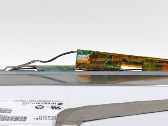
Carefully lift the display inverter board from the side nearest the display data cable connector.
-
-
Dieser Schritt ist noch nicht übersetzt. Hilf mit, ihn zu übersetzen!
-
Use your fingernails to pull the ears on both sides of the inverter cable connector away from its socket on the inverter board.
-
-
Dieser Schritt ist noch nicht übersetzt. Hilf mit, ihn zu übersetzen!
-
Carefully lift the display inverter out of the clutch cover.
-
-
Dieser Schritt ist noch nicht übersetzt. Hilf mit, ihn zu übersetzen!
-
Use your fingers to pull the backlight connector away from its socket on the inverter board.
-
Remove the display inverter from the display assembly.
-
-
-
Dieser Schritt ist noch nicht übersetzt. Hilf mit, ihn zu übersetzen!
-
Pull the display data cable straight away from its socket on the LCD.
-
-
Dieser Schritt ist noch nicht übersetzt. Hilf mit, ihn zu übersetzen!
-
Remove the four 3.2 mm Phillips screws securing the left side of the LCD assembly to the front display bezel.
-
-
Dieser Schritt ist noch nicht übersetzt. Hilf mit, ihn zu übersetzen!
-
Remove the four 3.2 mm Phillips screws from the top portion of the LCD assembly.
-
-
Dieser Schritt ist noch nicht übersetzt. Hilf mit, ihn zu übersetzen!
-
Remove the four 3.2 mm Phillips screws along the right side of the display.
-
-
Dieser Schritt ist noch nicht übersetzt. Hilf mit, ihn zu übersetzen!
-
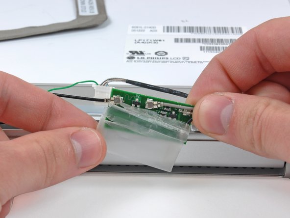
Carefully peel the protective translucent shield off the antenna board.
-
-
Dieser Schritt ist noch nicht übersetzt. Hilf mit, ihn zu übersetzen!
-
Use the flat end of a spudger to pry the the antenna cables straight up off their sockets.
-
-
Dieser Schritt ist noch nicht übersetzt. Hilf mit, ihn zu übersetzen!
-
Remove the single 2.5 mm Phillips screw securing the display data cable ground loop to the front display bezel.
-
-
Dieser Schritt ist noch nicht übersetzt. Hilf mit, ihn zu übersetzen!
-
Remove the two 10.3 mm T8 Torx screws securing the left side of the clutch hinges to the front bezel.
-
-
Dieser Schritt ist noch nicht übersetzt. Hilf mit, ihn zu übersetzen!
-
Remove the two 10.3 mm T8 Torx screws securing the center of the clutch hinges to the front bezel.
-
-
Dieser Schritt ist noch nicht übersetzt. Hilf mit, ihn zu übersetzen!
-
Remove the two 10.3 mm T8 Torx screws securing the right side of the clutch hinges to the front display bezel.
-
-
Dieser Schritt ist noch nicht übersetzt. Hilf mit, ihn zu übersetzen!
-
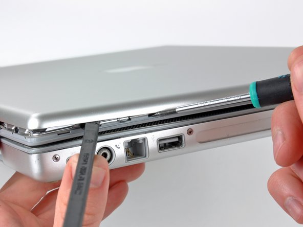
Press the display release button to release the top edge of the display from the upper case.
-
Carefully wiggle and lift the display assembly straight up off its positioning pins on the clutch hinges.
-
-
Dieser Schritt ist noch nicht übersetzt. Hilf mit, ihn zu übersetzen!
-
With the heat gun set to low, start by heating the front display bezel near the upper left corner of the display panel.
-
-
Dieser Schritt ist noch nicht übersetzt. Hilf mit, ihn zu übersetzen!
-
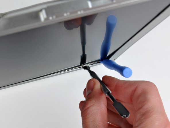
Insert a plastic opening tool between the metal LCD frame and the front bezel.
-
Use the flat end of a metal spudger to gently pry up the adhesive securing the metal LCD frame to the front bezel, taking special care not to scratch the LCD panel.
-
-
Dieser Schritt ist noch nicht übersetzt. Hilf mit, ihn zu übersetzen!
-
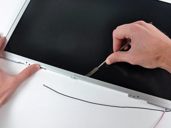
While it is still inserted between the metal LCD frame and the front bezel, run the edge of your metal spudger along the top edge of the display to separate the adhesive securing the two pieces together, heating the area you are working on with a heat gun as necessary.
-
-
Dieser Schritt ist noch nicht übersetzt. Hilf mit, ihn zu übersetzen!
-
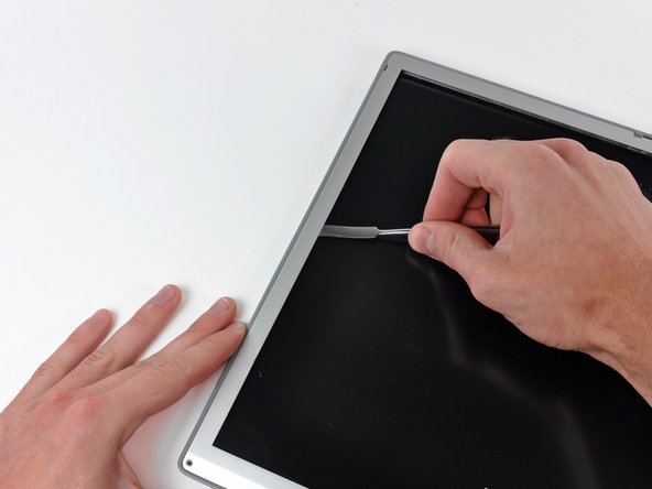
Continue running the edge of your metal spudger between the LCD frame and the front bezel until the right, bottom, and left sides of the LCD are free.
-
-
Dieser Schritt ist noch nicht übersetzt. Hilf mit, ihn zu übersetzen!
-
Lift the LCD out of the front display bezel, using your metal spudger to release any adhesive if necessary.
-
-
Dieser Schritt ist noch nicht übersetzt. Hilf mit, ihn zu übersetzen!
-
With the LCD partially removed from the front bezel, carefully push the backlight connector through its tunnel in the front bezel.
-


Rückgängig: Ich habe diese Anleitung nicht absolviert.
3 weitere Nutzer:innen haben diese Anleitung absolviert.
Angehängte Dokumente

2 Kommentare
This is not for the faint of heart I would not recommend doing this. Over 2 hours taking it apart another 2 putting it back. No real directions as to putting it back togeather. The Basel needs to be put on the top first for it has the most clips. Take a picture of it when you get it apart so you can see how to put everything back as in the cables and wires. This has got to be the worst design ever. Also for $20 replace the inverter board at the same time, so you don't have to take it apart again.
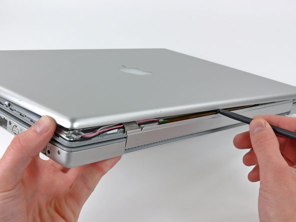
Do yourself a favor and remove the display assembly from the computer first.