Diese Version enthält möglicherweise inkorrekte Änderungen. Wechsle zur letzten geprüften Version.
Was du brauchst
-
Dieser Schritt ist noch nicht übersetzt. Hilf mit, ihn zu übersetzen!
-
Use your thumbs to push the two battery retaining tabs away from the battery.
-
The battery should pop up enough to rotate it toward yourself and lift it out of the lower case.
-
-
Dieser Schritt ist noch nicht übersetzt. Hilf mit, ihn zu übersetzen!
-
Remove the three 2.3 mm Phillips screws securing the memory cover to the lower case.
-
-
Dieser Schritt ist noch nicht übersetzt. Hilf mit, ihn zu übersetzen!
-
Lift the memory cover slightly and pull it toward yourself to remove it from the lower case.
-
-
Dieser Schritt ist noch nicht übersetzt. Hilf mit, ihn zu übersetzen!
-
Remove the following ten screws:
-
Two 14.7 mm shouldered Phillips.
-
Three 12.3 mm Phillips.
-
One 3.8 mm T8 Torx.
-
One 6.8 mm T8 Torx.
-
Three 1.3 mm Phillips.
-
-
Dieser Schritt ist noch nicht übersetzt. Hilf mit, ihn zu übersetzen!
-
Use your fingernails to separate the ZIF cable lock away from its socket. (Move the two brown bits down 1mm)
-
-
Dieser Schritt ist noch nicht übersetzt. Hilf mit, ihn zu übersetzen!
-
Use the tip of a spudger to slide the trackpad ribbon cable out of its socket.
-
-
Dieser Schritt ist noch nicht übersetzt. Hilf mit, ihn zu übersetzen!
-
Remove the four 3.4 mm Phillips screws from the PC card side of the PowerBook.
-
-
Dieser Schritt ist noch nicht übersetzt. Hilf mit, ihn zu übersetzen!
-
Remove the four 3.4 mm Phillips screws from the DVI connector side of the PowerBook.
-
-
Dieser Schritt ist noch nicht übersetzt. Hilf mit, ihn zu übersetzen!
-
Depress the display latch release button and open your display.
-
-
-
Dieser Schritt ist noch nicht übersetzt. Hilf mit, ihn zu übersetzen!
-
Starting near the display, lift the upper case straight up off the lower case, minding any cables that may get caught.
-
-
Dieser Schritt ist noch nicht übersetzt. Hilf mit, ihn zu übersetzen!
-
If necessary, peel back the strip of aluminum tape covering the modem cable.
-
-
Dieser Schritt ist noch nicht übersetzt. Hilf mit, ihn zu übersetzen!
-
Use the flat end of a spudger to pry the modem cable connector up off the modem.
-
-
Dieser Schritt ist noch nicht übersetzt. Hilf mit, ihn zu übersetzen!
-
Disconnect the RJ-11 cable from the modem.
-
-
Dieser Schritt ist noch nicht übersetzt. Hilf mit, ihn zu übersetzen!
-
Use a 4 mm nut driver to remove the two nuts securing the modem to the PC card cage.
-
-
Dieser Schritt ist noch nicht übersetzt. Hilf mit, ihn zu übersetzen!
-
Lift the modem straight up off the studs on the PC card cage.
-
-
Dieser Schritt ist noch nicht übersetzt. Hilf mit, ihn zu übersetzen!
-
Use the flat end of a spudger to pry the hard drive cable connector up off the logic board.
-
Bend the hard drive cable away from the PC card cage, giving yourself room to remove it.
-
-
Dieser Schritt ist noch nicht übersetzt. Hilf mit, ihn zu übersetzen!
-
Use the flat end of a spudger to pry the PC card cage connector up off the logic board.
-
-
Dieser Schritt ist noch nicht übersetzt. Hilf mit, ihn zu übersetzen!
-
Use the tip of a spudger to peel back the small strip of copper tape off the edge of the PC card cage near the side of the lower case.
-
-
Dieser Schritt ist noch nicht übersetzt. Hilf mit, ihn zu übersetzen!
-
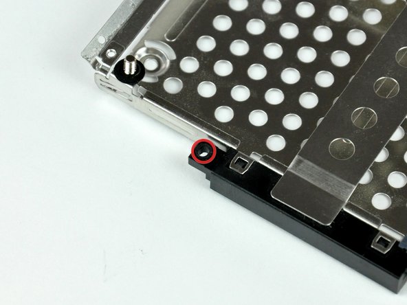
Remove the four Phillips screws (2- 4 mm & 2 -6.8 mm ) securing the PC card cage to the lower case.
-
-
Dieser Schritt ist noch nicht übersetzt. Hilf mit, ihn zu übersetzen!
-
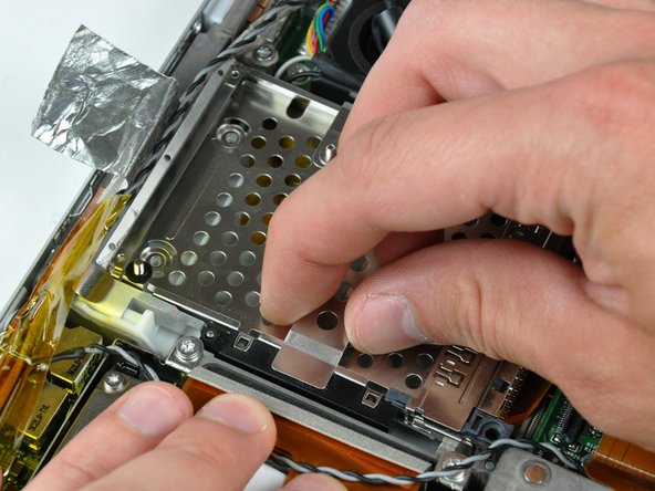
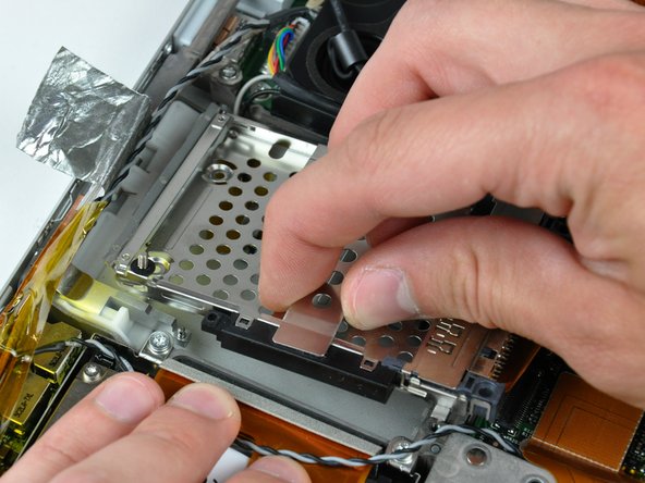
Lift the PC card cage by its center piece and maneuver it out of the lower case.
-
-
Dieser Schritt ist noch nicht übersetzt. Hilf mit, ihn zu übersetzen!
-
Use the flat end of a spudger to pry the ribbon cable connector up off the AirPort/Bluetooth board.
-
-
Dieser Schritt ist noch nicht übersetzt. Hilf mit, ihn zu übersetzen!
-
Remove the single 2.1 mm Phillips screw securing the AirPort/Bluetooth bracket to the lower case.
-
-
Dieser Schritt ist noch nicht übersetzt. Hilf mit, ihn zu übersetzen!
-
Use the flat end of a spudger to pry the AirPort/Bluetooth board up off the adhesive securing it to the lower case.
-
-
Dieser Schritt ist noch nicht übersetzt. Hilf mit, ihn zu übersetzen!
-
If necessary, remove the piece of tape and EMI foam covering the AirPort/Bluetooth antennas.
-
-
Dieser Schritt ist noch nicht übersetzt. Hilf mit, ihn zu übersetzen!
-
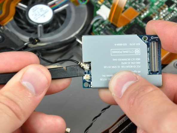
Use the flat end of a spudger to pry both antenna connectors up off the AirPort/Bluetooth board.
-


Rückgängig: Ich habe diese Anleitung nicht absolviert.
5 weitere Nutzer:innen haben diese Anleitung absolviert.
