Diese Version enthält möglicherweise inkorrekte Änderungen. Wechsle zur letzten geprüften Version.
Was du brauchst
-
Dieser Schritt ist noch nicht übersetzt. Hilf mit, ihn zu übersetzen!
-
Grasp the tail end of the drone where the lip of the battery protrudes.
-
-
Dieser Schritt ist noch nicht übersetzt. Hilf mit, ihn zu übersetzen!
-
Pull away from the drone to remove the battery.
-
-
Dieser Schritt ist noch nicht übersetzt. Hilf mit, ihn zu übersetzen!
-
To get into the drone, twelve total screws need to be removed:
-
Ten 5.7mm Phillips #000 screws from the bottom of the drone body.
-
Two 4.5mm Phillips #000 screws at the front of the drone.
-
-
-
Dieser Schritt ist noch nicht übersetzt. Hilf mit, ihn zu übersetzen!
-
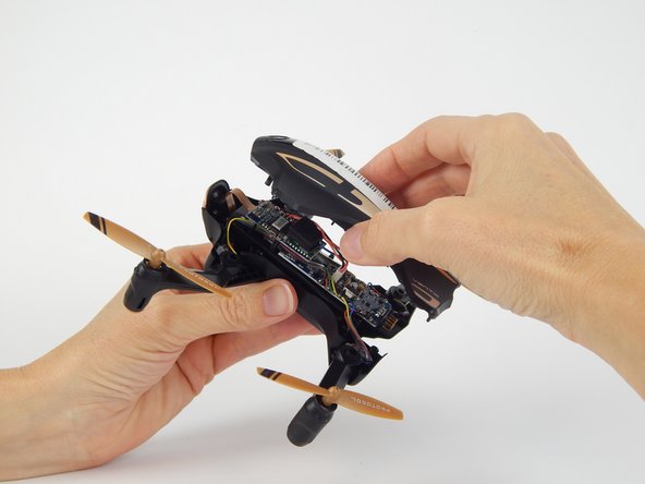
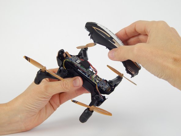
Flip the drone over and lift off the top plastic shell of the drone.
-
-
Dieser Schritt ist noch nicht übersetzt. Hilf mit, ihn zu übersetzen!
-
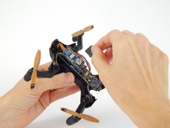
Remove the foam adhesive pad located on the Wi-Fi transmitter board.
-
-
Dieser Schritt ist noch nicht übersetzt. Hilf mit, ihn zu übersetzen!
-
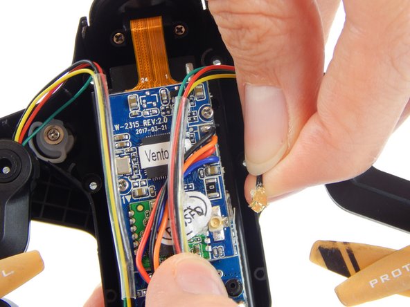
Pry the gold Wi-Fi antenna connector, located under the previously removed foam pad, away from the Wi-Fi transmitter board to disconnect it.
-
-
Dieser Schritt ist noch nicht übersetzt. Hilf mit, ihn zu übersetzen!
-
Remove the two 3.8mm Phillips #000 screws from the Wi-Fi transmitter board.
-
-
Dieser Schritt ist noch nicht übersetzt. Hilf mit, ihn zu übersetzen!
-
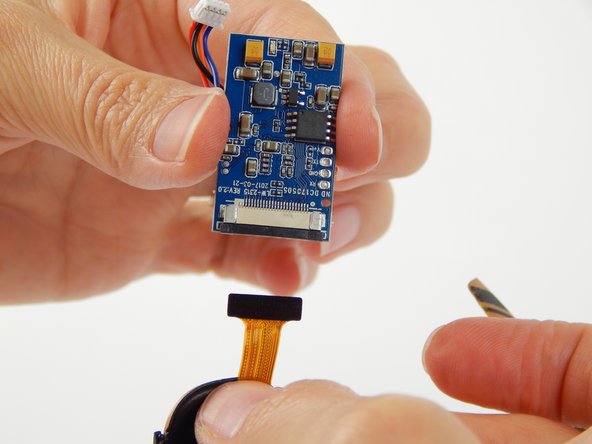
Disconnect the white clip that connects the four colored wires (black, orange, red, blue) to the motherboard.
-
-
Dieser Schritt ist noch nicht übersetzt. Hilf mit, ihn zu übersetzen!
-
Gently pull the black wedge away from the main board until it shifts to a stop. You will feel it slide out, then stop.
-
Lightly pull the ribbon cable away from the connector.
-


Rückgängig: Ich habe diese Anleitung nicht absolviert.
3 weitere Nutzer:innen haben diese Anleitung absolviert.
Team

USF Tampa, Team S1-G2, Leahy Spring 2018 Mitglied von USF Tampa, Team S1-G2, Leahy Spring 2018
USFT-LEAHY-S18S1G2
4 Mitglieder
6 Anleitungen geschrieben