Zum Hauptinhalt wechseln

Rain Bird ESP-6TM Control Board Replacement

Was du brauchst

  1. Rain Bird ESP-6TM Control Board Replacement, Replacing the control board: Schritt 1, Bild 1 von 3 Rain Bird ESP-6TM Control Board Replacement, Replacing the control board: Schritt 1, Bild 2 von 3 Rain Bird ESP-6TM Control Board Replacement, Replacing the control board: Schritt 1, Bild 3 von 3
    • Remove the lower plastic control box cover by gripping it with two hands and pulling it away from the control box.

    • Remove the plastic wire cover by gripping it with two hands and it pulling away from control box.

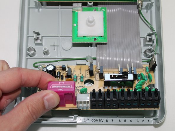
    • Remove the Lithium Ion battery by pulling out. The slide out battery compartment.

  2. Rain Bird ESP-6TM Control Board Replacement: Schritt 2, Bild 1 von 3 Rain Bird ESP-6TM Control Board Replacement: Schritt 2, Bild 2 von 3 Rain Bird ESP-6TM Control Board Replacement: Schritt 2, Bild 3 von 3
    • Grasp the control knob that is located at the center of the control box and pull it away from control box.

    • With two hands grasp the main control box cover and pull it away from the control box.

  3. Rain Bird ESP-6TM Control Board Replacement: Schritt 3, Bild 1 von 1
    • Use a Phillips #0 screwdriver to remove the four 6mm screws.

  4. Rain Bird ESP-6TM Control Board Replacement: Schritt 4, Bild 1 von 3 Rain Bird ESP-6TM Control Board Replacement: Schritt 4, Bild 2 von 3 Rain Bird ESP-6TM Control Board Replacement: Schritt 4, Bild 3 von 3
    • The snap connector must be cut free. It is best to use a razor blade, as the space is extremely limited. Cut on the top side and not the underside to insure it will snap back into place.

    • Place the razor blade on top of knob control board, sliding the razor blade underneath the snap connector. Then move the razor blade back and forth to remove the snap connector.

  5. Rain Bird ESP-6TM Control Board Replacement: Schritt 5, Bild 1 von 3 Rain Bird ESP-6TM Control Board Replacement: Schritt 5, Bild 2 von 3 Rain Bird ESP-6TM Control Board Replacement: Schritt 5, Bild 3 von 3
    • Using a spudger, release the clips holding the bottom control board. Then slide it downward while lifting control board away. This will separate the bottom of the control board from casing.

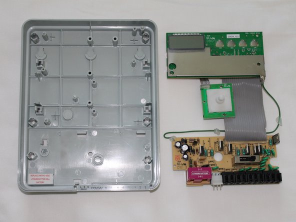
    • Once the bottom control board has been removed, simply lift the entire control board assembly away from the plastic casing. Then replace.

Abschluss

To reassemble your device, follow these instructions in reverse order.

Ein:e weitere:r Nutzer:in hat diese Anleitung absolviert.

Robert

Mitglied seit: 09/22/14

171 Reputation

1 Anleitung geschrieben

Team

USF Tampa, Team 1-4, Donnelly Fall 2014 Mitglied von USF Tampa, Team 1-4, Donnelly Fall 2014

USFT-DONNELLY-F14S1G4

1 Mitglied

1 Anleitung geschrieben

7 Kommentare

Can anyone who has one of these tell me what the shiny black disc component just above the purple lithium battery compartment is, and what values it is? My dad's has fried this component to crispy charcoal.

robin0 - Antwort

Some checking indicates it may be a metal oxide varistor, about 10mm diameter, but all the part numbers are burned away. Thanks for any help you can give me.

robin0 - Antwort

what happen if the screen said " PR OFF"

sergo legoute - Antwort

Why won’t the A/B switch work properly? I can program A and it works fine - manual or program; same with the B switch. However, when programmed to have B stations run after A stations, B station valves will not function

sob5th - Antwort

The PR off is indicated. The fuse was blown and when I replace the fuse with the dial in the off position and I then plug it in it keeps blowing the new fuses. Any suggestions.

Wayne - Antwort

Kommentar hinzufügen

Seitenaufrufe:

Letzte 24 Stunden: 3

Letzte 7 Tage: 16

Letzte 30 Tage: 51

Insgesamt: 10,751