Diese Version enthält möglicherweise inkorrekte Änderungen. Wechsle zur letzten geprüften Version.
Was du brauchst
-
Dieser Schritt ist noch nicht übersetzt. Hilf mit, ihn zu übersetzen!
-
Place the laptop upside down on a clean, flat surface.
-
Locate the battery release button with the padlock symbol above it.
-
Slide the battery release button towards the padlock symbol and hold it there. Note that the button is spring loaded and will return if released.
-
Gently remove the battery from the side of the laptop.
-
-
Dieser Schritt ist noch nicht übersetzt. Hilf mit, ihn zu übersetzen!
-
Place laptop upside down on a clean flat surface.
-
Remove 2ea M2.5 x 5 mm screws.
-
Pull the HDD from main body of the laptop.
-
-
Dieser Schritt ist noch nicht übersetzt. Hilf mit, ihn zu übersetzen!
-
Place laptop upsid down on a clean flat work surface.
-
Remove the Philips M2.5 x 8 mm screw
-
Loosen the screw that holds the memory compartment closed
-
remove the memory module compartment cover
-
Press the Optical Drive release lever to the right and the optical drive should slide out of the case
-
-
-
Dieser Schritt ist noch nicht übersetzt. Hilf mit, ihn zu übersetzen!
-
Use a spudger to lift the notched right edge of the hinge cover, and pry it loose
-
Lift the hinge cover off and set aside
-
-
Dieser Schritt ist noch nicht übersetzt. Hilf mit, ihn zu übersetzen!
-
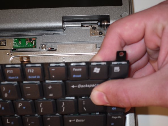
Remove 4ea M2 x 3mm keyboard screws
-
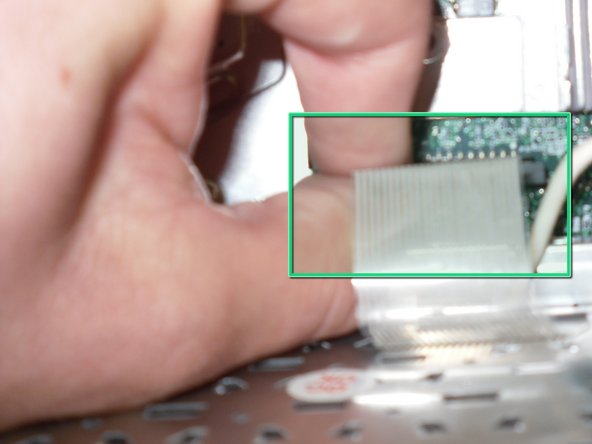
Lift up keyboard from the rear to expose the connector below
-
Disconnect the keyboard ribbon cable from the mother board
-
-
Dieser Schritt ist noch nicht übersetzt. Hilf mit, ihn zu übersetzen!
-
Remove 1ea M2.5 x 8mm screw holding the EMI shield in place
-
Remove the EMI shield to expose the LCD ribbon cable
-
Gently pull up on the tab to disconnect the ribbon cable from the main board
-
Close the lid carefully and remove the two M2.5 x 5-mm screws from the rear of the case
-
-
Dieser Schritt ist noch nicht übersetzt. Hilf mit, ihn zu übersetzen!
-
Remove 2e M2.5 x 5mm screws from each hinge bracket
-
The Display Assembly can now be lifted free of the laptop body
-


Rückgängig: Ich habe diese Anleitung nicht absolviert.
2 weitere Nutzer:innen haben diese Anleitung absolviert.
Team

Cal Poly, Team 16-2, Maness Spring 2010 Mitglied von Cal Poly, Team 16-2, Maness Spring 2010
CPSU-MANESS-S10S16G2
4 Mitglieder
9 Anleitungen geschrieben