Diese Version enthält möglicherweise inkorrekte Änderungen. Wechsle zur letzten geprüften Version.
Was du brauchst
-
Dieser Schritt ist noch nicht übersetzt. Hilf mit, ihn zu übersetzen!
-
Shut down the computer.
-
Wait 5 to 10 minutes to allow the computer’s internal components to cool.
-
Unplug all external cables from the computer except the power cord.
-
Touch the metal PCI access covers on the back of the computer to discharge any static electricity from your body.
-
Unplug the power cord.
-
Put on an ESD wrist strap.
-
-
Dieser Schritt ist noch nicht übersetzt. Hilf mit, ihn zu übersetzen!
-
1) Hold the side access panel and lift the latch on the back of the computer.
-
2) Remove the access panel and place it on a flat surface covered by a soft, clean cloth.
-
-
Dieser Schritt ist noch nicht übersetzt. Hilf mit, ihn zu übersetzen!
-
Type: Serial Attached SCSI (SAS) or Serial ATA (SATA) 3 Gb/s
-
Width: 3.9 inches (102 mm)
-
Depth: 5.7 inches (147 mm)
-
Height: 1.0 inch
-
-
Dieser Schritt ist noch nicht übersetzt. Hilf mit, ihn zu übersetzen!
-
Before you begin, open the computer, and lay it on its side with the access side facing up.
-
-
Dieser Schritt ist noch nicht übersetzt. Hilf mit, ihn zu übersetzen!
-
Make sure the latch on the back panel is up, so that the drives and carriers are unlocked.
-
Pull the hard drive out of the drive bay.
-
-
Dieser Schritt ist noch nicht übersetzt. Hilf mit, ihn zu übersetzen!
-
If you are replacing the hard drive with a new drive, remove the four screws that mount the 3. drive to the carrier and mount the new drive in the carrier.
-
-
Dieser Schritt ist noch nicht übersetzt. Hilf mit, ihn zu übersetzen!
-
This procedure explains how to remove a standard card and a card that includes a booster cable. Before you can remove either type of card, however, you must first loosen the two captive screws that secure the PCI bracket to the enclosure and remove the bracket.
-
-
Dieser Schritt ist noch nicht übersetzt. Hilf mit, ihn zu übersetzen!
-
1) Release the small locking clip at the front of the card’s logic board connector by pushing the clip up toward the media shelf.
-
2) Holding the card by the top corners, pull up the card and remove it from its expansion slot.
-
-
Dieser Schritt ist noch nicht übersetzt. Hilf mit, ihn zu übersetzen!
-
Disconnect the booster cable(s) from the logic board.
-
Release the small locking clip at the front of the card’s logic board connector by pushing the clip up toward the media shelf.
-
Holding the card by the top corners, gently pull up the card and remove it from its expansion slot.
-
-
Dieser Schritt ist noch nicht übersetzt. Hilf mit, ihn zu übersetzen!
-
Place the fingers of one hand under the lip of the heatsink cover nearest the logic board. Lift the lip slightly toward the media shelf to release the tabs and magnets under the top face of the cover.
-
With your fingers still under the cover’s bottom lip, lift the cover straight up to release the remaining tabs and magnets under the front face of the cover
-
Remove the cover from the enclosure.
-
-
Dieser Schritt ist noch nicht übersetzt. Hilf mit, ihn zu übersetzen!
-
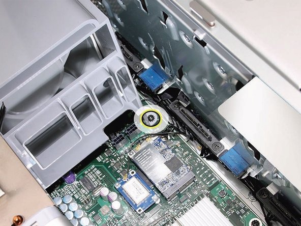
Using a long-handled, magnetized #1 Phillips screwdriver, remove the screw at the top rear of the front fan assembly that mounts the assembly to the logic board.
-
-
Dieser Schritt ist noch nicht übersetzt. Hilf mit, ihn zu übersetzen!
-
Remove the second Phillips screw at the bottom front of the assembly.
-
-
-
Dieser Schritt ist noch nicht übersetzt. Hilf mit, ihn zu übersetzen!
-
Place one hand on each end of the fan, lift straight up, and remove the fan from the enclosure.
-
-
Dieser Schritt ist noch nicht übersetzt. Hilf mit, ihn zu übersetzen!
-
Replacement Note: Also make sure the latch on the inside top left edge of the fan assembly engages with the slot on the inside lip of the enclosure
-
-
Dieser Schritt ist noch nicht übersetzt. Hilf mit, ihn zu übersetzen!
-
800 MHz, DDR2, FB-DIMMS
-
72-bit wide, 240-pin modules
-
36 memory ICs maximum per DIMM
-
Error-correcting code (ECC)
-
-
Dieser Schritt ist noch nicht übersetzt. Hilf mit, ihn zu übersetzen!
-
Holding the memory riser card by the two finger holes, pull it out of the memory cage and place the card DIMM side up on a soft, clean cloth.
-
-
Dieser Schritt ist noch nicht übersetzt. Hilf mit, ihn zu übersetzen!
-
Open the ejectors on the DIMM slot by pushing them out to the sides, and remove the DIMM from the riser card.
-
-
Dieser Schritt ist noch nicht übersetzt. Hilf mit, ihn zu übersetzen!
-
Disconnect the rear fan cable from the logic board.
-
-
Dieser Schritt ist noch nicht übersetzt. Hilf mit, ihn zu übersetzen!
-
Using a long-handled, magnetized #1 Phillips screwdriver, loosen the four captive screws that mount the memory cage to the logic board.
-
Rotate the computer so that it is standing vertically. Using a magnetized short-handled or right-angled jeweler’s #1 Phillips screwdriver, carefully remove the two short screws that mount the memory cage to the bottom panel of the enclosure.
-
-
Dieser Schritt ist noch nicht übersetzt. Hilf mit, ihn zu übersetzen!
-
Using your forefinger, reach below the fan and release the latch nearest the logic board.
-
-
Dieser Schritt ist noch nicht übersetzt. Hilf mit, ihn zu übersetzen!
-
Using a flat-blade screwdriver, release the two latches nearest the front of the computer.
-
-
Dieser Schritt ist noch nicht übersetzt. Hilf mit, ihn zu übersetzen!
-
Slide the rear fan into the memory cage.
-
-
Dieser Schritt ist noch nicht übersetzt. Hilf mit, ihn zu übersetzen!
-
Slide the memory cage and fan toward the power supply far enough that the cage clears the bottom edge of the enclosure. Then lift the memory cage and fan out of the enclosure.
-
-
Dieser Schritt ist noch nicht übersetzt. Hilf mit, ihn zu übersetzen!
-
Disconnect the 2-pin cable for the upper processor (CPU A) heatsink from the logic board.
-
-
Dieser Schritt ist noch nicht übersetzt. Hilf mit, ihn zu übersetzen!
-
Using a long-handled, magnetized 3 mm flathead hex screwdriver, loosen the four captive mounting screws for the upper processor heatsink in the order indicated below.
-
Lift the heatsink straight up and out of the enclosure.
-
-
Dieser Schritt ist noch nicht übersetzt. Hilf mit, ihn zu übersetzen!
-
Disconnect the cable connector for the lower processor (CPU B) heatsink.
-
-
Dieser Schritt ist noch nicht übersetzt. Hilf mit, ihn zu übersetzen!
-
Using a long-handled, magnetized 3 mm flathead hex screwdriver, loosen the four captive mounting screws for the lower processor heatsink in the order indicated below.
-
Carefully tilt the heatsink so that it clears the bottom lip of the enclosure and then lift the heatsink out of the computer.
-
-
Dieser Schritt ist noch nicht übersetzt. Hilf mit, ihn zu übersetzen!
-
Preparing an EXISTING Heatsink for Re-installation. If you have a new heatsink, follow the NEW Heatsink procedure.
-
Using the alcohol pad included with the logic board or processor replacement part, clean off any used thermal grease from the processor and the bottom of the heatsink.
-
Using the thermal grease included with the logic board or processor replacement part, apply one dot of fresh grease to the raised square area on the bottom of the heatsink.
-
Spread the grease evenly across the square to a thickness of approximately 1 mm.
-
-
Dieser Schritt ist noch nicht übersetzt. Hilf mit, ihn zu übersetzen!
-
Preparing a New Heatsink for Re-installation. If you have a existing heatsink, follow the EXISTING Heatsink procedure.
-
Apply the top gasket included in the parts box to the top of the heatsink.
-
If you are replacing the lower processor heatsink with a new heatsink, install the bumper included in the parts box on the side of the heatsink.
-
-
Dieser Schritt ist noch nicht übersetzt. Hilf mit, ihn zu übersetzen!
-
Use the following guidelines when handling the processor heatsink and/or processor:
-
Wear disposable nitrile or latex gloves
-
Avoid touching the silver-colored coating on the underside of the heatsink and the top of the processor.
-
Always make a visual inspection of new or existing heatsinks and processors before installing them in the computer.
-
When removing or replacing the heatsink and/or processor, do not allow the heatsink to be separated from the processor for more than 30 minutes. The special coating on the heatsink and processor degrades with exposure to air; more than 30 minutes exposure could result in damage to the computer and a repeat, multi-part repair.
-
-
Dieser Schritt ist noch nicht übersetzt. Hilf mit, ihn zu übersetzen!
-
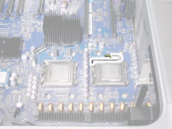
Release the latch on the metal processor holder.
-
-
Dieser Schritt ist noch nicht übersetzt. Hilf mit, ihn zu übersetzen!
-
Rotate the top of the holder to the open position.
-
Lift the processor out of the holder.
-


Rückgängig: Ich habe diese Anleitung nicht absolviert.
62 weitere Nutzer:innen haben diese Anleitung absolviert.

8 Kommentare
Hi there! Can you recommend which processor best fit with my machine: QUAD CORE XEON 3.0 (intel) 2.1 (mid 2008) with LION (10.7.6). I wish to run El Captain (10.11) or Sierra (10.12)..
Hey, buddy, how you doing?
Has a problem with your Mac Pro 2008
After the device is turned on for a few seconds, it is stopped
Please, what's the problem?
Hi!
I just bought a 2008 3,1 MacPro with 1cpu and I was wondering if it is possible that I can add a 2nd cpu… Do I have to order another Heatsink or anything else?
You will need a matching processor, a heat sink, (be careful to get the muliti copper pipes for a 3,1, not eh 1,1 or 2,1 although the older ones will work, it wont be matching), and some thermal paste.
If you are getting the 3.2 2 processor upgrade, then you will need 2 new 3.2 specific heat sinks. See the guide above for those.
Also you will need a long 3mm hex head screw driver. The Ifixit drivers barley worked.