Diese Version enthält möglicherweise inkorrekte Änderungen. Wechsle zur letzten geprüften Version.
Was du brauchst
-
Dieser Schritt ist noch nicht übersetzt. Hilf mit, ihn zu übersetzen!
-
Insert a SIM card eject tool, bit, or a straightened paperclip into the small hole in the SIM card tray.
-
Press to eject the tray.
-
-
Dieser Schritt ist noch nicht übersetzt. Hilf mit, ihn zu übersetzen!
-
Remove the SIM card tray from the phone.
-
-
Dieser Schritt ist noch nicht übersetzt. Hilf mit, ihn zu übersetzen!
-
Insert an opening pick between the screen and the back cover on the bottom of the phone where the charging port is located.
-
-
Dieser Schritt ist noch nicht übersetzt. Hilf mit, ihn zu übersetzen!
-
Slide the opening pick to the bottom left corner to release the clips.
-
-
Dieser Schritt ist noch nicht übersetzt. Hilf mit, ihn zu übersetzen!
-
Slide the opening pick along the left edge to the top left corner of the phone, to release the clips.
-
-
Dieser Schritt ist noch nicht übersetzt. Hilf mit, ihn zu übersetzen!
-
Slide the opening pick from the top left corner to the top right corner to release the plastic clips.
-
-
Dieser Schritt ist noch nicht übersetzt. Hilf mit, ihn zu übersetzen!
-
Slide the opening pick from the top right corner to the bottom right corner to release the remaining clips.
-
-
-
Dieser Schritt ist noch nicht übersetzt. Hilf mit, ihn zu übersetzen!
-
Remove screws from the motherboard antenna cover.
-
3 Phillips #00, 3mm length.
-
-
Dieser Schritt ist noch nicht übersetzt. Hilf mit, ihn zu übersetzen!
-
Use the tip of a spudger or tweezers to remove the antenna cover.
-
-
Dieser Schritt ist noch nicht übersetzt. Hilf mit, ihn zu übersetzen!
-
Remove screws from the motherboard cover.
-
3 Phillips #00, 3mm length
-
-
Dieser Schritt ist noch nicht übersetzt. Hilf mit, ihn zu übersetzen!
-
Use the tip of a spudger or tweezers to remove the motherboard cover.
-
-
Dieser Schritt ist noch nicht übersetzt. Hilf mit, ihn zu übersetzen!
-
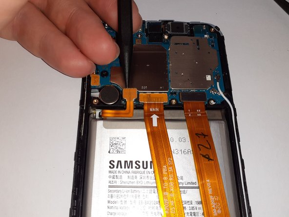
Use a spudger to disconnect the battery by prying the connector straight up from its socket.
-
-
Dieser Schritt ist noch nicht übersetzt. Hilf mit, ihn zu übersetzen!
-
Gently flex the battery connector away from its socket.
-
-
Dieser Schritt ist noch nicht übersetzt. Hilf mit, ihn zu übersetzen!
-
Remove screws from daughterboard cover.
-
7 Phillips #00, 3mm length.
-
-
Dieser Schritt ist noch nicht übersetzt. Hilf mit, ihn zu übersetzen!
-
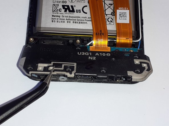
Use a pair of tweezers to lift up the bottom of the daughterboard cover to a ~30 degree angle.
-
Pull the daughterboard cover straight out, away from the phone.
-
-
Dieser Schritt ist noch nicht übersetzt. Hilf mit, ihn zu übersetzen!
-
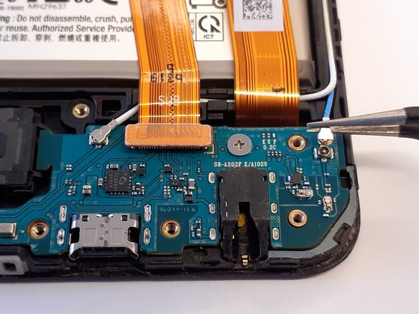
Insert the flat end of a spudger under the interconnect flex connector, and gently pry it straight up.
-
-
Dieser Schritt ist noch nicht übersetzt. Hilf mit, ihn zu übersetzen!
-
Using a pair of tweezers, gently disconnect one of the antenna connectors.
-
-
Dieser Schritt ist noch nicht übersetzt. Hilf mit, ihn zu übersetzen!
-
Using a pair of tweezers, gently disconnect the other antenna connector.
-
-
Dieser Schritt ist noch nicht übersetzt. Hilf mit, ihn zu übersetzen!
-
Remove screw from daughterboard.
-
1 Phillips #00, 2mm length.
-


Rückgängig: Ich habe diese Anleitung nicht absolviert.
12 weitere Nutzer:innen haben diese Anleitung absolviert.
2 Kommentare
a common issue with the A10E is the phone notifying you that you have water damage in the usb type-C port this can be fixed by replacing the daughter board which has a IC which is commonly faulty.
From where can you obtain a new daughterboard?