Diese Version enthält möglicherweise inkorrekte Änderungen. Wechsle zur letzten geprüften Version.
Was du brauchst
-
Dieser Schritt ist noch nicht übersetzt. Hilf mit, ihn zu übersetzen!
-
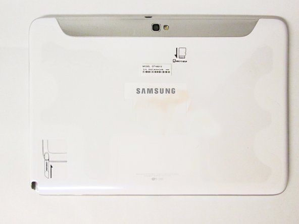
This is the back of the device and where you willl begin to take it apart.
-
It is necessary to remove the silver piece covering the camera first before removing the bigger back piece.
-
Use the plastic opening tools to pry along the indicated box.
-
Lift up the silver piece to reveal the rest of the back cover.
-
-
Dieser Schritt ist noch nicht übersetzt. Hilf mit, ihn zu übersetzen!
-
Unscrew the three 5 mm screws indicated by the red circles with the Philips #00 screwdriver.
-
Using the plastic opening tools pry along the bottom of the device, moving to the sides of the cover to the top.
-
Remove the back cover.
-
-
Dieser Schritt ist noch nicht übersetzt. Hilf mit, ihn zu übersetzen!
-
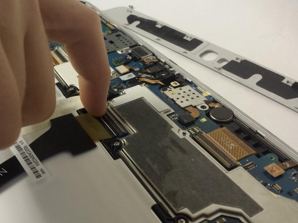
Carefully remove all of the ribbons that connect over the battery from the locations indicated by the yellow circles.
-
-
Dieser Schritt ist noch nicht übersetzt. Hilf mit, ihn zu übersetzen!
-
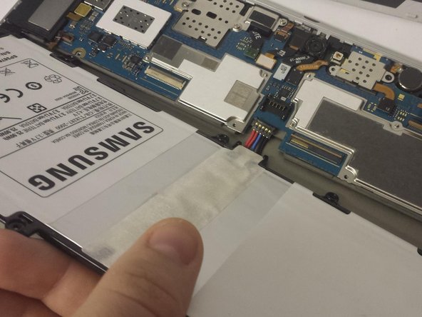
Remove all of the 3 mm screws indicated by a red circle with the #00 Philips screwdriver.
-
Disconnect the battery from the location indicated by a yellow circle
-
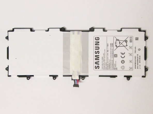
Now you may remove the battery.
-
-
-
Dieser Schritt ist noch nicht übersetzt. Hilf mit, ihn zu übersetzen!
-
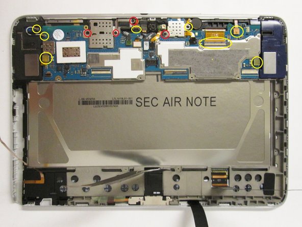
From the first photo:
-
Remove all the components marked by yellow circles
-
Unscrew all the 3 mm and 2 mm screws marked by the red circles with the #00 Philips screwdriver.
-
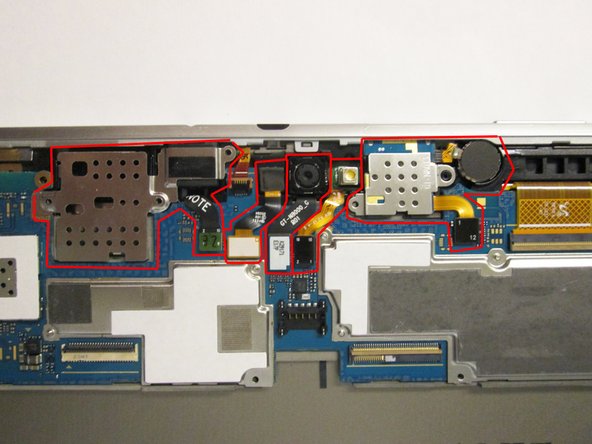
From the second photo:
-
Starting with the motherboard connectors, remove all the components marked in red.
-
-
Dieser Schritt ist noch nicht übersetzt. Hilf mit, ihn zu übersetzen!
-
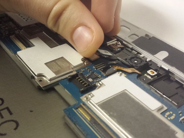
Once you have removed all the components connected to the motherboard, gently lift up on the area surrounding the green box and remove your motherboard.
-
-
Dieser Schritt ist noch nicht übersetzt. Hilf mit, ihn zu übersetzen!
-
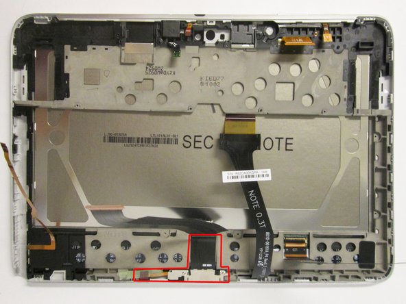
Apply pressure to the locations boxed in red to remove the loudspeaker modules.
-
-
Dieser Schritt ist noch nicht übersetzt. Hilf mit, ihn zu übersetzen!
-
From the first photo:
-
Unscrew the 2 mm screws marked by red circles with the #00 Philips screwdriver.
-
Be sure to lift the tape marked by the yellow circle from the frame.
-
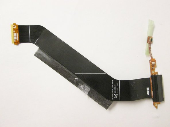
Gently pry the ribbon from the frame and lift the charging port from the frame.
-
-
Dieser Schritt ist noch nicht übersetzt. Hilf mit, ihn zu übersetzen!
-
Starting from the under the right speaker casing, use one plastic prying tool to start lifting up on the LCD frame.
-
Use two of the plastic prying tools, one for support and the other for prying, to completely separate the LCD casing from the digitizer frame.
-
-
Dieser Schritt ist noch nicht übersetzt. Hilf mit, ihn zu übersetzen!
-
Gently tear the LCD from its frame by lifting it from the tape connecting the two.
-
-
Dieser Schritt ist noch nicht übersetzt. Hilf mit, ihn zu übersetzen!
-
Remove the ribbon indicated by the yellow box and place it on your replacement LCD screen.
-


Rückgängig: Ich habe diese Anleitung nicht absolviert.
28 weitere Nutzer:innen haben diese Anleitung absolviert.
Team

USF Tampa, Team 3-7, Brown Fall 2014 Mitglied von USF Tampa, Team 3-7, Brown Fall 2014
USFT-BROWN-F14S3G7
3 Mitglieder
9 Anleitungen geschrieben
4 Kommentare
In Step 7, mention that you should use the plastic tools to pop the speakers out of the device.
In the final step, I would not say that you should "tear" the screen out ("gently remove" would probably be better)
Very detailed and allowed me to successfully replace the broken LCD screen on my Galaxy Note. Thanks!