Einleitung
Diese Anleitung zeigt, wie die Displayeinheit im Samsung Galaxy Note9 ausgetauscht werden kann.
Was du brauchst
-
-
Drücke unten auf den S-Pen bis es leise klickt.
-
Lasse den S-Pen los, er kommt von selbst aus dem Gerät heraus.
-
Ziehe den S-Pen heraus.
-
-
-
Setze ein SIM-Auswurfwerkzeug oder eine aufgebogene Büroklammer in die Öffnung am SIM-Karteneinschub ein.
-
Drücke darauf, bis der Einschub herauskommt.
-
-
-
Schalte das Gerät aus, bevor du mit der Demontage beginnst.
-
Benutze einen Föhn, Heißluftgebläse oder einen erhitzten iOpener und erhitze damit die rechte Kante der Rückseite des Geräts für ca. eine Minute, um den Klebstoff darunter zu lösen.
If using an iOpener it will need to be fully heated and set on for at least 5 minutes. You’ll know the phone is hot enough when its almost too hot to touch.
Just came here to say exactly that. The instructions should be amended to state that: "Get it fully hot and leave it there for at least three minutes solid."
-
-
-
Setze einen Saugheber auf die Rückseite auf.
-
Hebe die Rückseite mit dem Saugheber soweit hoch, dass eine Lücke zwischen der Rückseite und dem Rahmen des Gerätes entsteht.
-
Schiebe nun ein Plektrum in den Spalt.
It takes so much heat that it is concerning that damage might be caused to the internal parts. It is difficult to heat the glue, pull the case apart and insert the pick at same time. May need some more pointers to handle these situations first, to prevent possible damage. Also what about the glue that is heated and then cooled before opening? Does it run inside and cause greater adhesion after it cools? Another thing, the handling may cause the phone to turn back on while working to separate. Don't know that that is of concern.
-
-
-
Beachte, dass an der Oberkante und rund um die Kamera mehr Klebstoff ist, als am restlichen Gerät.
-
Durchtrenne den Kleber sehr vorsichtig in der Nähe des Fingerabdrucksensors, da sonst das Flachbandkabel im Inneren beschädigt werden könnte.
It's extremely easy to crack the back glass when nearing and rounding the corners. It's probably a good idea to soften the adhesive with heat as you go.
Step 5 is NOT "cut through the adhesive", that's steps 5-10. Step 5 is "Begin the careful process of cutting through the adhesive, starting at the right side where you already softened it. Proceed carefully, slowly, and warmly through the following steps."
These comments are spot-on. I never break a phone, and I cracked the back glass following the instructions without seeing these comments first. Heat the back much more than you think you need and go super, super slow.
-
-
-
Beginne in der Mitte und durchtrenne den Klebstoff mit dem Plektrum. Schiebe es mehrfach hoch und runter.
-
-
-
Lasse ein Plektrum in der oberen rechten Ecke stecken.
-
Verwende ein weiteres Plektrum, um den Klebstoff an der unteren rechten Ecke zu lösen.
-
Lasse das Plektrum im Smartphone stecken.
There seems to be a lot of glue at the bottom, I broke the glass as I was cutting past the charging port - not sure if it was already fractured or just not enough heat (I used Sellotape so it didn't break up into pieces!)
I think LOTS of heat & patience is the key!
Be very careful around the corners and bottom (probably top too, but I didn't have a problem there). Make sure you've cut in far enough down the side first (go in about 1cm) but less round the corners and work in slowly.
-
-
-
Verwende einen Föhn, ein Heißluftgebläse oder einen iOpener um den Klebstoff an der linken Rückseite aufzuweichen. Erhitze die Stelle für ca. eine Minute.
If using an iOpener it will need to be fully heated and set on for at least 5 minutes. You’ll know the phone is hot enough when its almost too hot to touch.
-
-
-
Schiebe ein Plektrum in die untere linke Ecke der Rückseite.
-
Mit einem weiteren Plektrum schneide den Klebstoff an der linken Kante der Rückabdeckung entlang.
-
-
-
Schneide mit den eingesteckten Plektrum vorsichtig an der oberen linken Ecke des Geräts den Klebstoff durch.
-
Letztenendes schneide das letzte Stück Klebstoff mit einem Plektrum durch.
Be VERY patient as you slide the opening picks around the periphery of the glass, and use heat very liberally. Make sure the smooth, clear aspect of the iOpener is against the glass, not the rough black portion.
-
-
-
Hebe die rechte Seite der Rückseite zuerst hoch.
-
Kippe die Rückseite an der linken Seite hoch, sodass du das Flachbandkabel des Fingerabdrucksensors sehen kannst.
Thought I'd done something wrong here as there wasn't a cable attached to the back - the fingerprint reader hadn't come away with the back, but had stayed with the phone.
Exactly the same experience. Made life a little easier.
Happened to me as well.
-
-
-
Benutze die Spitze des Spudgers, um das Flachbandkabel des Fingerabdrucksensors nach oben aus seinem Anschluss zu hebeln.
-
-
-
Entferne die Rückseite.
-
Entferne jegliche Rückstände des Klebers vom Gehäuse des Geräts. Säubere dann die Flächen mit hoch konzentriertem Isopropylalkohol (mind. 90%) und einem fusselfreien Tuch, um die Oberfläche für den neuen Kleber vorzubereiten.
-
Trage vorsichtig den neuen Kleber auf die abgetrennte Rückseite des Geräts auf. Richte nun eine Glaskante am Rahmen des Geräts aus und drücke die Rückseite in das Gehäuse.
I am installing a new backplate (this is my first repair; I was CERTAIN that I would crack the back glass, and I was NOT wrong) but I’m not sure how tweezers are meant to remove gooey adhesive! I simply used the blue plastic pry tool as a scraper and gently rolled up the goo. Maybe the glue is different because I have a refurbished phone? That may also explain why I had so much trouble with Step 1. Hope that this helps!
-
-
-
Schritt 15 Oberen Mittelrahmen entfernen
Achtung: Die Schritte 15-18 stammen von einer Anleitung, die derzeit bearbeitet wird.
-
Entferne die neun 4 mm Kreuzschlitzschrauben, mit denen der obere Mittelrahmen befestigt ist.
There are two more screws on the bottom right corner of the little side frame that the Qi plate is glued to. I took those out as it put less stress on it.
It helps to hold the fine tweezers with your non-dominant hand to support the screw heads and ensure they come straight out; you can also gently lift as you unscrew.
-
-
-
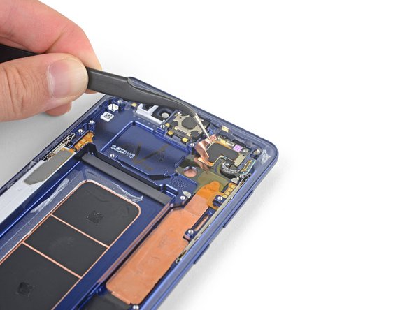
Setze die Spudgerspitze in die obere linke Ecke des oberen Mittelrahmens ein.
-
Heble den oberen Mittelrahmen aus dem Smartphone heraus.
-
-
-
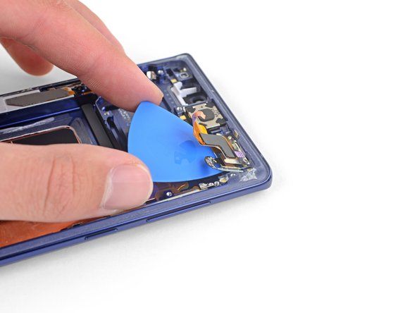
Löse die drahtlose Ladespule von der linken Seite beginnend vom Akku ab.
-
-
-
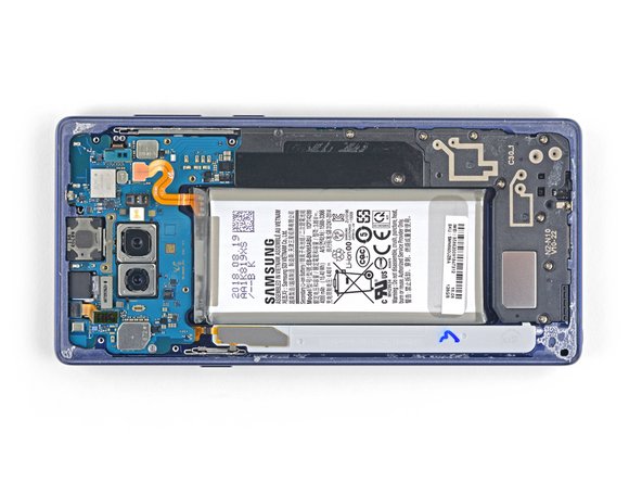
Trenne das orangene Flachbandkabel, mit dem der Akku an der Hauptplatine angeschlossen ist, mit der Spudgerspitze ab.
-
-
-
Entferne die neun 4 mm Kreuzschlitzschrauben von der Kunststoffabdeckung nahe am Akku.
-
-
-
Setze die Spudgerspitze oben am unteren Mittelrahmen ein.
-
Heble den unteren Mittelrahmen aus dem Smartphone heraus.
-
Entferne den unteren Mittelrahmen.
-
-
-
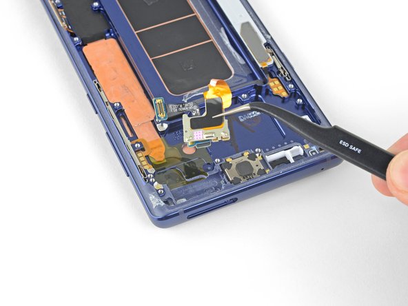
Heble den Stecker der Frontkamera mit der Spudgerspitze gerade nach oben aus seinem Anschluss hoch.
-
Entferne die Frontkamera mit einer Pinzette.
-
-
-
Trenne den Irisscanner mit der Spudgerspitze von der Hauptplatine ab.
-
Entferne den Irisscanner mit einer Pinzette.
-
-
-
Heble den Stecker der Frontsensoren mit dem flachen Ende des Spudgers aus seinem Anschluss heraus.
-
-
-
Trenne das Displaykabel mit dem flachen Ende des Spudgers von der Hauptplatine ab.
-
-
-
Trenne das Touchscreenkabel mit dem flachen Ende des Spudgers von der Hauptplatine ab.
-
-
-
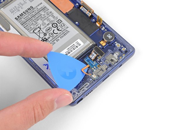
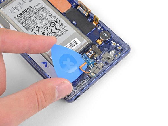
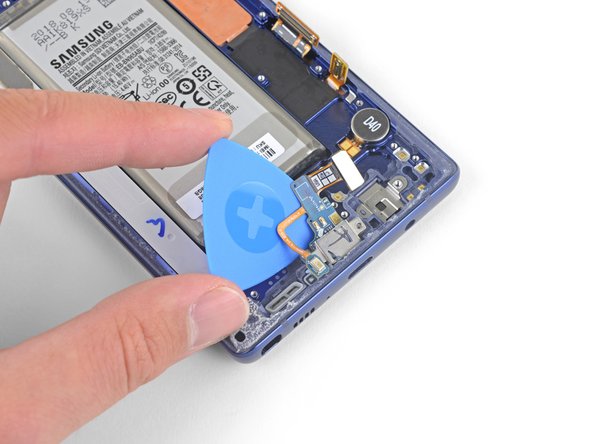
Trenne die Ladeeinheit mit dem flachen Ende des Spudgers von der Hauptplatine ab.
These screws are supposed to be 3.2 mm because when I took out these screws, they were shorter than the ones you take out first
-
-
-
Entferne die drei 4 mm Kreuzschlitzschrauben, mit denen die Hauptplatine befestigt ist.
-
-
-
Hebe die Hauptplatine an der oberen linken Ecke behutsam mit dem Spudger hoch.
-
Entferne vorsichtig die Hauptplatine.
-
-
-
Entferne die 3,2 mm Kreuzschlitzschraube von der Kopfhörerbuchse.
-
-
-
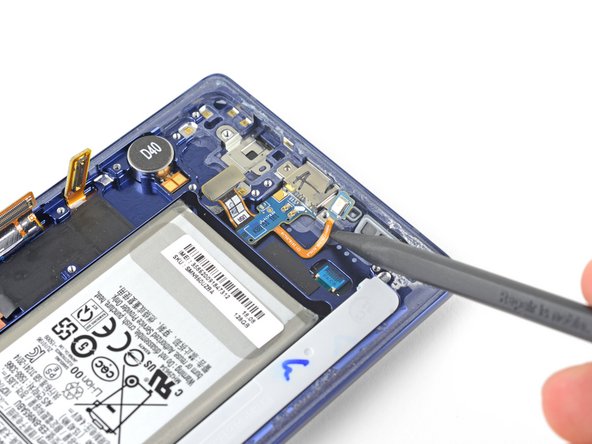
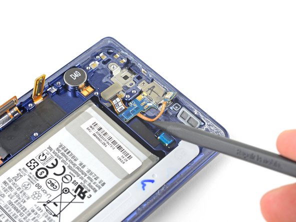
Setze die Spudgerspitze in die Einbuchtung nahe bei den Kontakten der Kopfhörerbuchse ein.
-
Heble die Kontaktplatine gerade nach oben und löse sie aus der Klebeverbindung darunter.
-
-
-
Entferne die Kopfhörerbuchseneinheit mit einer Pinzette.
-
-
-
Entferne die beiden 3,2 mm Kreuzschlitzschrauben von der Ladeeinheit.
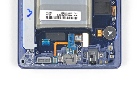
Please add a step that mentions the round item labeled “D40”. It, similarly to the headphone jack, is tediously removed by adding some isopropyl alcohol to the groove above/under it and then sliding a spudger or tweezers into the same groove. Slowly wiggle it with your prod while the isopropyl alcohol does its job.
This is necessary If your new display assembly does not include the vibration motor (labeled D40). The pointed end of a spudger may not be small enough to get leverage under it, so use angled tweezers if you have to.
-
-
-
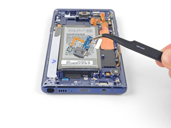
Entferne die Ladeeinheit mit einer Pinzette.
-
-
-
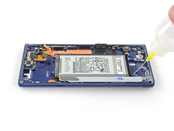
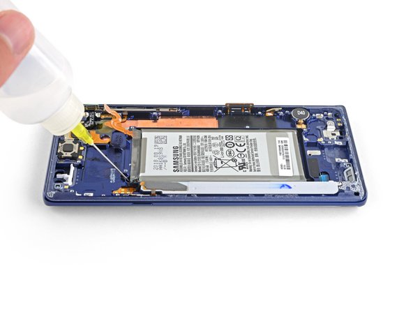
Tröpfle etwas 90%igen Isopropylalkohol an der Unterkante und der oberen linken Ecke in die Vertiefung für den Akku ein.
-
Lasse den Alkohol einige Minuten lang einwirken, bis der Kleber unter dem Akku aufgeweicht ist.
-
Halte das Gerät in verschiedenen Schräglagen gekippt, damit der Alkohol unter den Akku läuft.
-
-
-
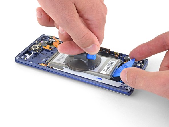
Befestige einen Saugheber am Akku.
-
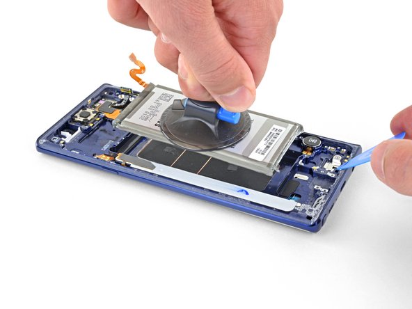
Hebe den Akku soweit gerade nach oben, so dass ein Spalt entsteht, in den du ein Plektrum einsetzen kannst.
-
Setze ein Plektrum unter die Unterkante des Akkus ein und verdrehe es, so dass sich der Kleber am Akku löst.
-
Entferne den Akku.
-
-
-
Ziehe die angeklebte Kupferfolie mit einer Pinzette zurück.
-
Löse sie nicht weiter ab, wenn du an der Frontsensorgruppe angekommen bist.
-
-
-
Hebe die linke Seite der Frontsensorgruppe mit dem Spudger an und löse den restlichen Kleber ab.
-
-
-
Schiebe sorgfältig ein Plektrum unter dem Flachbandkabel zur Frontsensorgruppe entlang, um die Klebeverbindung darunter aufzutrennen.
-
-
-
Entferne die Frontsensorgruppe mit einer Pinzette.
Buen día, excelente tutorial...sigan con ese mismo interes...Bendiciones para todo el grupo.
Desde Santa Cruz, Bolivia.
-


Um dein Gerät wieder zusammenzubauen, folge den Schritten dieser Anleitung in umgekehrter Reihenfolge.
Entsorge deinen Elektromüll fachgerecht.
Lief die Reparatur nicht wie geplant? In unserem Forum findest du Hilfe bei der Fehlersuche.
Vergleiche dein Ersatzteil mit dem Originalteil - möglicherweise musst du fehlende Bauteile übertragen oder Schutzfolien am Neuteil abziehen, bevor du es einbauen kannst.
Rückgängig: Ich habe diese Anleitung nicht absolviert.
46 weitere Nutzer:innen haben diese Anleitung absolviert.
Besonderer Dank geht an diese Übersetzer:innen:
100%
VauWeh hilft uns, die Welt in Ordnung zu bringen! Wie kann ich mithelfen?
Hier starten ›

15 Kommentare
Make sure you transfer over the vibration motor if the new frame does not have it… didn’t realize my replacement didn’t have it until I put the glass back on :/
Thank you for pointing this out! I almost missed it! I wish this guide showed how to put it back together instead of just saying “okay now do it again but backwards.” Anyway, I appreciate this comment right here haha.
The guide assumes that you have a new display unit containing all the parts that are left after the last step (display, front glass, screen, cooling system, vibration motor and so on.)
Since replacement parts vary from seller to seller, you’ll have to compare yours to the original and transfer any remaining components. This guide was written for the display assembly that we were selling at the time.
When transferring other components such as the vibration motor just be sure to use the same methods as with similar components. Work slowly, always use heat or ≥90% isopropyl alcohol to soften adhesives, and search the internet for more information as necessary.
But what about the actual replacement of the display screen? The instructions stops at removing the front sensor array
Because it is an OLED screen the entire assembly has to be replaced. If the guide is followed and the part was purchased from iFixit, once the front sensor array is removed you can begin working backwards transferring all components into the new display assembly. Unfortunately replacing the screen from the front is not possible. If you purchase the part from somewhere other than iFixit you may need to transfer additional components.
The guide does not explain how to glue the front and back together once everything is put back together.
Do I have to buy a specific glue or does the new part have pre-applied glue and do I need heat to activate?
Thanks
The new part most likely won’t have pre-installed adhesive. This generic perimeter adhesive guide for Samsung Galaxy phones will help!
Any suggestions on getting the suction cup to stick to the battery? I cant seem to get mine to hold.
I just flooded the battery space with rubbing alcohol and let it sit for a minute. Then the battery more or less lifted out. If you still think you need it a smaller suction cup or even dental floss to run under the battery may help.
It was very informative and clear. Thank You.
Hello! I would ask, but the display is the same for version 128 or 512gb, right?
I have never had a digitizer not power on. Is it just a bad digitizer or what? I also brought a new battery.
The gasket and adhesive kit came with a great set of components. However it's not clear when and where they are put. Would be nice if iFixit had notes about these for reassembly.