Diese Version enthält möglicherweise inkorrekte Änderungen. Wechsle zur letzten geprüften Version.
Was du brauchst
-
-
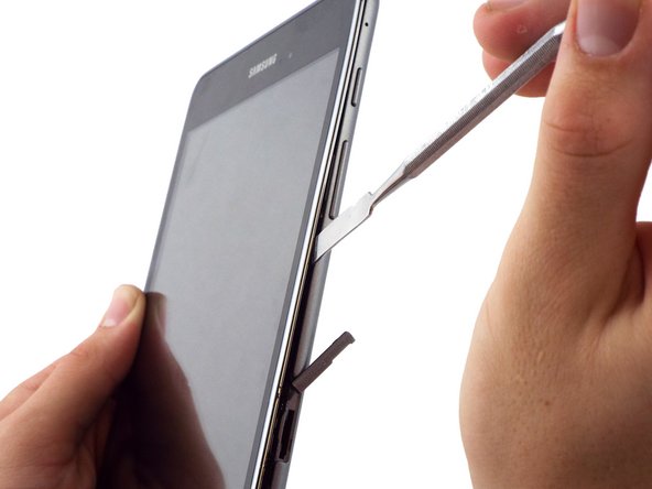
Setze einen metallenen Spatel am oberen Ende des Speicherkartenschlitzes an um einen Spalt zwischen der Rückabdeckung und dem Gehäuse zu schaffen.
-
-
-
Löse mit einem mittleren Spatel anstelle des kleinen Spatels die Rückabdeckung ab. Das erreichst du indem du den Spatel vom oberen Ende des Speicherkartenschlitzes ausgehend ringsum führst.
-
Das zweite Bild zeigt das Innere nachdem die Rückabdeckung abgenommen worden ist.
-
-
-
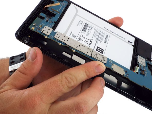
Hebele den Akku mit dem flachen Ende eines Spudgers aus dem Gerät.
-
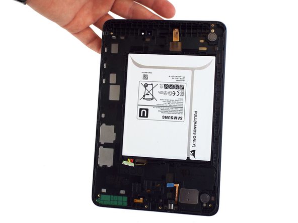
Wenn die Rückabdeckung und der Akku entfernt sind sieht das Gerät aus wie in Bild 2.
-
-
-
Dieser Schritt ist noch nicht übersetzt. Hilf mit, ihn zu übersetzen!
-
Use a spudger to lift up and release the press-fit display cable connector from the motherboard.
-
-
Dieser Schritt ist noch nicht übersetzt. Hilf mit, ihn zu übersetzen!
-
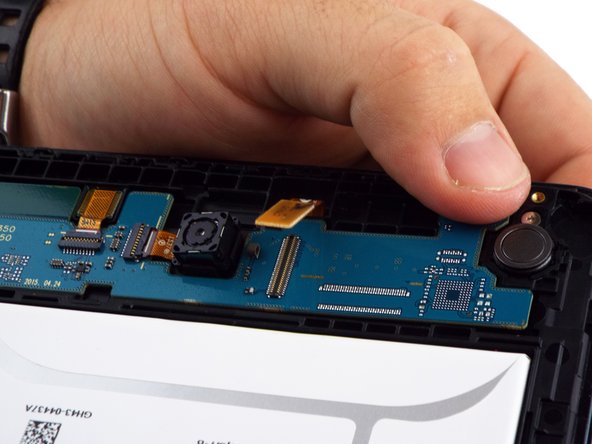
Use a spudger to lift up and release the ZIF connector; gently pull the rear facing camera ribbon cable free.
-
Use a pair of tweezers to gently secure the camera and lift it out of the frame.
-
-
Dieser Schritt ist noch nicht übersetzt. Hilf mit, ihn zu übersetzen!
-
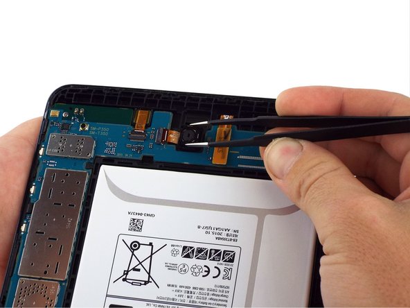
Use a spudger to flip the front-facing camera ZIF connector up; gently pull the ribbon cable free.
-
Use tweezers to gently remove the front facing camera from the frame.
-
-
Dieser Schritt ist noch nicht übersetzt. Hilf mit, ihn zu übersetzen!
-
Use the flat end of a spudger to lift up and disconnect the LCD screen press-fit connector.
-
-
Dieser Schritt ist noch nicht übersetzt. Hilf mit, ihn zu übersetzen!
-
Use the flat end of a spudger to lift up and disconnect the 3.5mm headset jack press-fit connector.
-
-
Dieser Schritt ist noch nicht übersetzt. Hilf mit, ihn zu übersetzen!
-
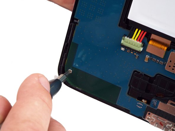
Use a PH000 screwdriver to remove the two 3 mm screws that connect the USB port shield to the midframe.
-
-
Dieser Schritt ist noch nicht übersetzt. Hilf mit, ihn zu übersetzen!
-
Use a PH000 screwdriver to remove the two 3 mm screws on the left side of the motherboard.
-
-
Dieser Schritt ist noch nicht übersetzt. Hilf mit, ihn zu übersetzen!
-
Lift the motherboard free from the power and volume button side.
-
You may use a spudger to assist in gently lifting the motherboard up from the button side.
-
A small plastic bracket secures the motherboard to the frame; lift the motherboard from the power and volume button side first, and slide away from the bracket.
-


Rückgängig: Ich habe diese Anleitung nicht absolviert.
13 weitere Nutzer:innen haben diese Anleitung absolviert.


3 Kommentare
Where is the rest of this guide? Just stops after removing motherboard :[
It appears that it is intended to remove all parts from the case (battery and motherboard) and install them in a new body with a good screen attached.
Ben D -
After removing the motherboard, I continued with disassembly by following the iFixit guide for the Digitizer removal.
( Samsung Galaxy Tab A Digitizer Replacement )
After removing the glass/digitizer, I was able to remove the LCD relatively easy by pushing it through the gaps on the back end of the frame. It appeared to not have any adhesive holding it in place. I was replacing the LCD and the digitizer in my case so I was I bit more careless with the removal of those components. I did place a bit of adhesive on the new LCD replacement and everything fit back snuggly.