Diese Version enthält möglicherweise inkorrekte Änderungen. Wechsle zur letzten geprüften Version.
Was du brauchst
-
Dieser Schritt ist noch nicht übersetzt. Hilf mit, ihn zu übersetzen!
-
Turn the camera off by pressing the small, square button embedded in the top rim of the camera.
-
Locate the battery hatch on the bottom-right side of the camera and slide it outwards to open.
-
In the compartment, move the small notch and push down on the battery to remove it.
-
-
Dieser Schritt ist noch nicht übersetzt. Hilf mit, ihn zu übersetzen!
-
Remove the eight screws around the sides and bottom of the camera using a Phillips #00 screwdriver.
-
-
Dieser Schritt ist noch nicht übersetzt. Hilf mit, ihn zu übersetzen!
-
Using the spudger, gently pry the rear panel away from the left side.
-
-
Dieser Schritt ist noch nicht übersetzt. Hilf mit, ihn zu übersetzen!
-
Using the Phillips #00 screwdriver, remove the eight black screws connecting the green keypad chip to the rear panel.
-
-
Dieser Schritt ist noch nicht übersetzt. Hilf mit, ihn zu übersetzen!
-
Separate the rear panel from the rest of the camera.
-
-
-
Dieser Schritt ist noch nicht übersetzt. Hilf mit, ihn zu übersetzen!
-
Using the Phillips #00 screwdriver, remove the 3 screws located across the top of the camera.
-
Separate the black plastic panel from the camera. The camera button will be attached, so be gentle.
-
-
Dieser Schritt ist noch nicht übersetzt. Hilf mit, ihn zu übersetzen!
-
Carefully pull off the side covers wrapped around the camera.
-
-
Dieser Schritt ist noch nicht übersetzt. Hilf mit, ihn zu übersetzen!
-
Using the spudger, gently lift off the front cover of the camera.
-
-
Dieser Schritt ist noch nicht übersetzt. Hilf mit, ihn zu übersetzen!
-
The yellow ribbon is attached to the right side of the screen and goes to a black connector piece.
-
Gently flip the black connector away from the LCD screen to unlock the yellow ribbon.
-
Carefully pull the yellow ribbon towards the LCD screen to disconnect it.
-
-
Dieser Schritt ist noch nicht übersetzt. Hilf mit, ihn zu übersetzen!
-
The LCD screen should now be disconnected from the rest of the camera and a pry tool can be used to lift it out of its casing.
-
-
Dieser Schritt ist noch nicht übersetzt. Hilf mit, ihn zu übersetzen!
-
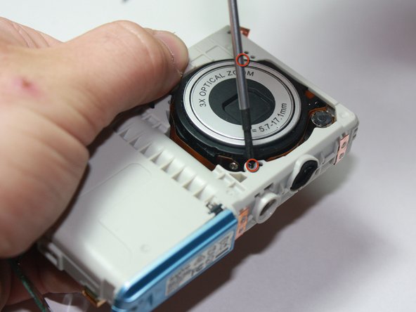
Flip the camera over with the lens facing up.
-
-
Dieser Schritt ist noch nicht übersetzt. Hilf mit, ihn zu übersetzen!
-
Using the Phillips #00 Screwdriver, remove the two screws holding the lens in place.
-
-
Dieser Schritt ist noch nicht übersetzt. Hilf mit, ihn zu übersetzen!
-
While keeping hold of the lens, flip the entire assembly around.
-
Using your fingers, gently push the lens out from its position in the casing.
-
-
Dieser Schritt ist noch nicht übersetzt. Hilf mit, ihn zu übersetzen!
-
Carefully unplug the golden wire from the motherboard to remove the lens from the assembly.
-


Rückgängig: Ich habe diese Anleitung nicht absolviert.
Ein:e weitere:r Nutzer:in hat diese Anleitung absolviert.
Team

Cal Poly, Team 27-95, Amido Spring 2010 Mitglied von Cal Poly, Team 27-95, Amido Spring 2010
CPSU-AMIDO-S10S27G95
4 Mitglieder
4 Anleitungen geschrieben