Zum Hauptinhalt wechseln
Gemeinsam reparieren - Jetzt registrieren

Sega Dreamcast GD-ROM Replacement

Was du brauchst

    1. Sega Dreamcast GD-ROM Replacement, Expansion Bay: Schritt 1, Bild 1 von 2 Sega Dreamcast GD-ROM Replacement, Expansion Bay: Schritt 1, Bild 2 von 2
      • Verify that the console is disconnected from the AC outlet before you begin.

      • Flip the console over on its back.

      • Take note of your model number, in case replacement parts are needed.

      Frag FixBot

      Kommentar hinzufügen

    2. Sega Dreamcast GD-ROM Replacement: Schritt 2, Bild 1 von 3 Sega Dreamcast GD-ROM Replacement: Schritt 2, Bild 2 von 3 Sega Dreamcast GD-ROM Replacement: Schritt 2, Bild 3 von 3
      • Remove the expansion bay by applying pressure to the small clip on the expansion bay while prying it away from the console.

      Frag FixBot

      Kommentar hinzufügen

    1. Sega Dreamcast GD-ROM Replacement, Top Cover: Schritt 3, Bild 1 von 1
      • Locate and remove all four black 12mm Phillips #02 screws from the underside of the console.

      • Note: Remove the expansion bay to locate the fourth screw

      Frag FixBot

      Kommentar hinzufügen

    2. Sega Dreamcast GD-ROM Replacement: Schritt 4, Bild 1 von 1
      • Internal components can be loose. Be careful that they do not fall out when removing the cover.

      • Turn the console right side up.

      • Remove the top cover by gently lifting the upper portion of the console.

      Frag FixBot

      Kommentar hinzufügen

    1. Sega Dreamcast GD-ROM Replacement, GD-ROM: Schritt 5, Bild 1 von 2 Sega Dreamcast GD-ROM Replacement, GD-ROM: Schritt 5, Bild 2 von 2
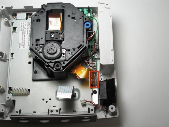
      • Detach the orange cable by giving it a gentle pull while wiggling the cable back and forth until it loosens from the logic board.

      Frag FixBot

      Kommentar hinzufügen

    2. Sega Dreamcast GD-ROM Replacement: Schritt 6, Bild 1 von 2 Sega Dreamcast GD-ROM Replacement: Schritt 6, Bild 2 von 2
      • Detach the cables by gently pulling the three GD-ROM cables to remove them from the logic board.

      Frag FixBot

      Kommentar hinzufügen

    3. Sega Dreamcast GD-ROM Replacement: Schritt 7, Bild 1 von 2 Sega Dreamcast GD-ROM Replacement: Schritt 7, Bild 2 von 2
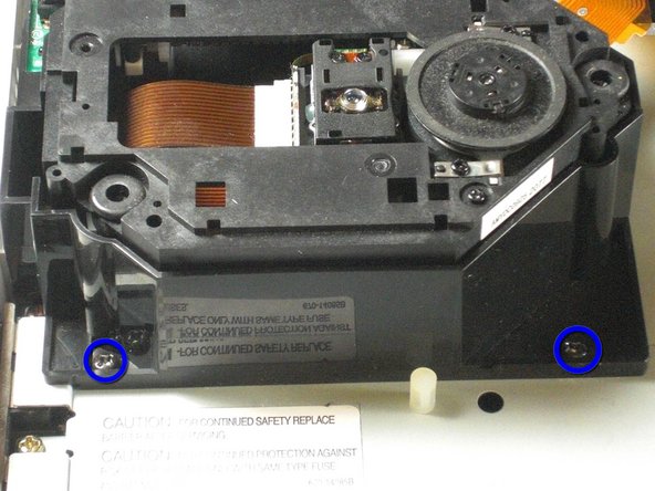
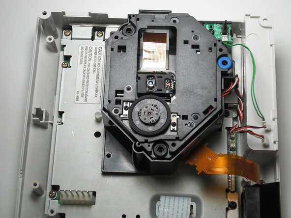
      • Remove the two black 12mm Philips #02 screws located on the left side of the GD-ROM bracket.

      • The console is rotated 90 degrees counter-clockwise in the first photo. The second photo depicts the normal position.

      Frag FixBot

      Kommentar hinzufügen

    4. Sega Dreamcast GD-ROM Replacement: Schritt 8, Bild 1 von 2 Sega Dreamcast GD-ROM Replacement: Schritt 8, Bild 2 von 2
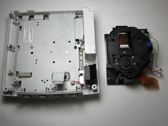
      • When lifting the GD-ROM, be careful that the top half of the casing does not detached from its base.

      • Remove the GD-ROM by gently lifting it from its base.

      Frag FixBot

      Kommentar hinzufügen

    1. Sega Dreamcast GD-ROM Replacement, GD-ROM: Schritt 9, Bild 1 von 2 Sega Dreamcast GD-ROM Replacement, GD-ROM: Schritt 9, Bild 2 von 2
      • Replace the bad GD-ROM drive with a functional one.

      Frag FixBot

      Kommentar hinzufügen

    2. Sega Dreamcast GD-ROM Replacement: Schritt 10, Bild 1 von 2 Sega Dreamcast GD-ROM Replacement: Schritt 10, Bild 2 von 2
      • Secure the new GD-ROM drive to the console with the Philips #2 screws.

      Frag FixBot

      Kommentar hinzufügen

    3. Sega Dreamcast GD-ROM Replacement: Schritt 11, Bild 1 von 3 Sega Dreamcast GD-ROM Replacement: Schritt 11, Bild 2 von 3 Sega Dreamcast GD-ROM Replacement: Schritt 11, Bild 3 von 3
      • Connect the three GD-ROM cables to the logic board.

      • Connect the GD-ROM data ribbon to the logic board.

      Frag FixBot

      Kommentar hinzufügen

Ziellinie

Rückgängig: Ich habe diese Anleitung nicht absolviert.

10 weitere Personen haben diese Anleitung absolviert.

Team

Cal Poly, Team 5-1, Regan Fall 2009 Mitglied von Cal Poly, Team 5-1, Regan Fall 2009

CPSU-REGAN-F09S5G1

5 Mitglieder

109 Anleitungen geschrieben

2 Kommentare zur Anleitung

If only it was that simple Sega screwed U.K gamers over with the fact we have to buy totally new consoles due to the wires of the disk drive being soldered in rather than clipped in.

Anthony Salmon - Antwort Teilen

My HKT-3020 console, NTSC-U revision 1, manufactured in Japan during 4/2000, does not have the orange cable shown in step 5. I was able to skip steps 5 and 6, and for step 7 I had to remove 3 screws, not 2. My GD-ROM drive came as an assembly, mounted on a metal plate; the entire assembly simply lowers into a connector port. After removing the screws, I just had to gently wiggle it up and out of the port, then lower the replacement assembly into the same port, and replace the 3 screws.

Aaron Teplitsky - Antwort Teilen

Kommentar hinzufügen

Seitenaufrufe:

Letzte 24 Stunden: 11

Letzte 7 Tage: 72

Letzte 30 Tage: 353

Insgesamt: 39,356